Tag: TCP OSI Model

Time Out Timer | Karn Algorithm | Jacobson Algorithm

TCP Timers-


Before you go through this article, make sure that you have gone through the previous article on TCP Timers.


We have discussed-

  • TCP Timers are used to avoid excessive delays during communication.
  • Several timers used in a TCP implementation are-
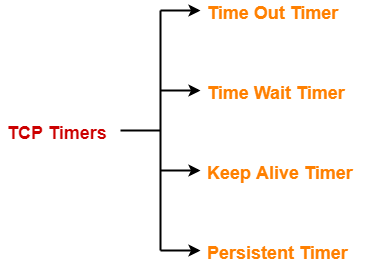


  1. Time Out Timer
  2. Time Wait Timer
  3. Keep Alive Timer
  4. Persistent Timer


In this article, we will discuss about Time Out Timer and its Computation.


Time Out Timer-


TCP uses a time out timer for retransmission of lost segments.


  • Sender starts a time out timer after transmitting a TCP segment to the receiver.
  • If sender receives an ACK before the timer goes off, it stops the timer.
  • If sender does not receives any ACK and the timer goes off, then TCP Retransmission occurs.
  • Sender retransmits the same segment and resets the timer.
  • The value of time out timer is dynamic and changes with the amount of traffic in the network.


Network Traffic And Time Out Timer-


Consider-

  • Receiver has sent the ACK to the sender.
  • The ACK is on its way through the network.


Now, following two cases are possible-


Case-01: High traffic-


If there is high traffic in the network-

  • The time taken by the ACK to reach the sender will be more.
  • So, as per the high traffic, the value of time out timer should be kept large.


If the value is kept small, then-

  • Timer will time out soon.
  • It causes the sender to assume that the segment is lost before reaching the receiver.
  • However, in actual the ACK is delayed due to high traffic.
  • Sender keeps retransmitting the same segment.
  • This overburdens the network and might lead to congestion.


Case-02: Low traffic-


If there is low traffic in the network-

  • The time taken by the ACK to reach the sender will be less.
  • So, as per the low traffic, the value of time out timer should be kept small.


If the value is kept large,

  • Timer will not time out soon.
  • Sender keeps waiting for the ACK even when it is actually lost.
  • This causes excessive delay.


Conclusion-


The value of time out timer should be such that-

  • It decreases when there is low traffic traffic in the network.
  • It increases when there is high traffic in the network.


Algorithms For Computing Time Out Timer Value-


The algorithms used for computing the value of time out timer dynamically are-

  1. Basic Algorithm
  2. Jacobson’s Algorithm
  3. Karn’s modification


Rules


All the above algorithms work on the following rules-


Rule-01:


The value of time out timer for the next segment is increased when-

  • Actual round trip time for the previous segment is found to be increased indicating there is high traffic in the network.


Rule-02:


The value of time out timer for the next segment is decreased when-

  • Actual round trip time for the previous segment is found to be decreased indicating there is low traffic in the network.


Now, let us see all the algorithms one by one.


Basic Algorithm-


The steps followed under Basic Algorithm are-


Step-01: Sending 1st Segment-


While sending the 1st segment,

  • Sender assumes any random value of initial RTT say IRTT1.
  • So after sending the 1st segment, sender expects its ACK to arrive in time IRTT1.
  • Sender sets time out timer value (TOT) for the 1st segment to be-


TOT1 = 2 X IRTT1


  • Suppose ACK for the 1st segment arrives in time ARTT1.
  • Here, ARTT1 = Actual Round Trip Time for the 1st segment.


Step-02: Sending 2nd Segment-


While sending the 2nd segment,

  • Sender computes the value of initial RTT for the 2nd segment using the relation-


IRTTn+1 = α IRTTn + (1 – α)ARTTn


Here, α is called smoothing factor where 0 <= α <= 1

(Its value will be given in questions)


Now,

  • Substituting n=1, sender gets IRTT2 = α IRTT1 + (1 – α)ARTT1.
  • So after sending the 2nd segment, sender expects its ACK to arrive in time IRTT2.
  • Sender sets time out timer value (TOT) for the 2nd segment to be-


TOT2 = 2 X IRTT2


  • Suppose ACK for the 2nd segment arrives in time ARTT2.
  • Here, ARTT2 = Actual Round Trip Time for the 2nd segment.


In the similar manner, algorithm computes the time out timer value for all the further segments.


Advantages-


The advantages of Basic Algorithm are-

  • Time out timer value is flexible to dynamic round trip time.
  • It takes into consideration all the previously sent segments to derive the initial RTT for the current segment.


Disadvantage-


The disadvantage of Basic Algorithm is-

  • It always considers Time out timer value = 2 x Initial round trip time.
  • There is no logic behind using the number 2.


2. Jacobson’s Algorithm-


  • Jacobson’s Algorithm is a modified version of the basic algorithm.
  • It gives better performance than Basic Algorithm.


The steps involved in Jacobson’s Algorithm are-


Step-01: Sending 1st Segment-


While sending the 1st segment,

  • Sender assumes any random value of initial RTT say IRTT1.
  • So after sending the 1st segment, sender expects its ACK to arrive in time IRTT1.
  • Sender assumes any random value of initial deviation say ID1.
  • So after sending the 1st segment, sender expects there will be a deviation of ID1 time from IRTT1.
  • Sender sets time out timer value (TOT) for the 1st segment to be-


TOT1 = 4 x ID1 + IRTT1


  • Suppose ACK for the 1st segment arrives in time ARTT1.
  • Here, ARTT1 = Actual Round Trip Time for the 1st segment.
  • Then, Actual deviation from IRTT1 is given by-

AD1 = | IRTT1 – ARTT1 |


Step-02: Sending 2nd Segment-


While sending the 2nd segment,

  • Sender computes the value of initial RTT for the 2nd segment using the relation-


IRTTn+1 = α IRTTn + (1 – α)ARTTn


Here, α is called smoothing factor where 0 <= α <= 1

(Its value will be given in questions)

  • Sender computes the value of initial deviation for the 2nd segment using the relation-


IDn+1 = α IDn + (1 – α)ADn


Here, α is called smoothing factor where 0 <= α <= 1

(Its value will be given in questions)

  • Substituting n=1, sender gets-

IRTT2 = α IRTT1 + (1 – α)ARTT1

ID2 = α ID1 + (1 – α)AD1


  • So after sending the 2nd segment, sender expects its ACK to arrive in time IRTT2 with deviation of IDtime.
  • Sender sets time out timer value (TOT) for the 2nd segment to be-


TOT2 = 4 x ID2 + IRTT2


  • Suppose ACK for the 2nd segment arrives in time ARTT2.
  • Here, ARTT2 = Actual Round Trip Time for the 2nd segment.
  • Then, Actual deviation from IRTT2 is given by-

AD2 = | IRTT2 – ARTT2 |


In the similar manner, algorithm computes the time out timer value for all the further segments.


Problems with Basic Algorithm and Jacobson’s Algorithm-


To calculate initial round trip time, both the algorithms depend on the actual round trip time of the previous segment through the relation-


IRTTn+1 = α IRTTn + (1 – α)ARTTn


Now,

  • Consider ACK of some segment arrives to the sender after its initial time out timer goes off.
  • Then, sender will have to re transmit the segment.
  • Now for the segment being re transmitted, what should be the initial time out timer value is the concern.
  • This is because the ACK is delayed and will arrive after time out.
  • So, ARTT is not available.


This problem is resolved by Karn’s modification.


3. Karn’s Modification-


Karn’s modification states-

  • Whenever a segment has to be re transmitted, do not apply either of Basic or Jacobson’s algorithm since actual RTT is not available.
  • Instead, double the time out timer (TOT) whenever the timer times out and make a retransmission.


NOTE

In the above discussion,

Initial time out timer value may also be called as the estimated time out timer value for the segment being sent.


PRACTICE PROBLEMS BASED ON CALCULATING TIME OUT TIMER VALUE-


Problem-01:


In TCP, the initial RTT is 10 msec. The acknowledgements for the first three segments are received in time 15 msec, 20 msec and 10 msec.

Find the time out timer value for the first four segments using basic algorithm. Use α = 0.5.


Solution-


For 1st Segment-


Initial round trip time (IRTT1) = 10 msec


So, Time out timer value (TOT1)

= 2 x IRTT1

= 2 x 10

= 20 msec


Now,

  • ACK for the 1st segment is received after 15 msec.
  • So, Actual round trip time (ARTT1) = 15 msec.


For 2nd Segment-


Initial round trip time (IRTT2)

= α x IRTT1 + (1-α) x ARTT1

= 0.5 x 10 + (1-0.5) x 15

= 5 + 7.5

= 12.5 msec


So, Time out timer value (TOT2)

= 2 x IRTT2

= 2 x 12.5

= 25 msec


Now,

  • ACK for the 2nd segment is received after 20 msec.
  • So, Actual round trip time (ARTT2) = 20 msec.


For 3rd Segment-


Initial round trip time (IRTT3)

= α x IRTT2 + (1-α) x ARTT2

= 0.5 x 12.5 + (1-0.5) x 20

= 6.25 + 10

= 16.25 msec


So, Time out timer value (TOT3)

= 2 x IRTT3

= 2 x 16.25

= 32.5 msec


Now,

  • ACK for the 3rd segment is received after 10 msec.
  • So, Actual round trip time (ARTT3) = 10 msec.


For 4th Segment-


Initial round trip time (IRTT4)

= α x IRTT3 + (1-α) x ARTT3

= 0.5 x 16.25 + (1-0.5) x 10

= 8.125 + 5

= 13.125 msec


So, Time out timer value (TOT4)

= 2 x IRTT4

= 2 x 13.125

= 26.25 msec


Problem-02:


In TCP, the initial RTT is 10 msec and the initial deviation is 5 msec. The acknowledgements for the first three segments are received in time 20 msec, 30 msec and 10 msec.

Find the time out timer value for the first four segments using Jacobson’s Algorithm. Use α = 0.5.


Solution-


For 1st Segment-


  • Initial round trip time (IRTT1) = 10 msec
  • Initial deviation (ID1) = 5 msec


So,

Time out timer value (TOT1)

= 4 x ID1 + IRTT1

= 4 x 5 + 10

= 30 msec


Now, ACK for the 1st segment is received after 20 msec. So,

  • Actual round trip time (ARTT1) = 20 msec
  • Actual deviation (AD1) = | IRTT1 – ARTT1 | = | 10 – 20 | = 10 msec


For 2nd Segment-


Initial round trip time (IRTT2)

= α x IRTT1 + (1-α) x ARTT1

= 0.5 x 10 + (1-0.5) x 20

= 5 + 10

= 15 msec


Initial deviation (ID2)

= α x ID1 + (1-α) x AD1

= 0.5 x 5 + (1-0.5) x 10

= 2.5 + 5

= 7.5 msec


So, Time out timer value (TOT2)

= 4 x ID2 + IRTT2

= 4 x 7.5 + 15

= 45 msec


Now, ACK for the 2nd segment is received after 30 msec. So,

  • Actual round trip time (ARTT2) = 30 msec
  • Actual deviation (AD2) = | IRTT2 – ARTT2 | = | 15 – 30 | = 15 msec


For 3rd Segment-


Initial round trip time (IRTT3)

= α x IRTT2 + (1-α) x ARTT2

= 0.5 x 15 + (1-0.5) x 30

= 7.5 + 15

= 22.5 msec


Initial deviation (ID3)

= α x ID2 + (1-α) x AD2

= 0.5 x 7.5 + (1-0.5) x 15

= 3.75 + 7.5

= 11.25 msec


So, Time out timer value (TOT3)

= 4 x ID3 + IRTT3

= 4 x 11.25 + 22.5

= 67.5 msec


Now, ACK for the 3rd segment is received after 10 msec. So,

  • Actual round trip time (ARTT3) = 10 msec
  • Actual deviation (AD3) = | IRTT3 – ARTT3 | = | 22.5 – 10 | = 12.5 msec


For 4th Segment-


Initial round trip time (IRTT4)

= α x IRTT3 + (1-α) x ARTT3

= 0.5 x 22.5 + (1-0.5) x 10

= 11.25 + 5

= 16.25 msec


Initial deviation (ID3)

= α x ID3 + (1-α) x AD3

= 0.5 x 11.25 + (1-0.5) x 12.5

= 5.625 + 6.25

= 11.875 msec


So, Time out timer value (TOT4)

= 4 x ID4 + IRTT4

= 4 x 11.875 + 16.25

= 63.75 msec


Next Article- Silly Window Syndrome


Get more notes and other study material of Computer Networks.

Watch video lectures by visiting our YouTube channel LearnVidFun.

Silly Window Syndrome | Nagle’s Algorithm

Silly Window Syndrome-


  • Silly Window Syndrome is a problem that arises due to the poor implementation of TCP.
  • It degrades the TCP performance and makes the data transmission extremely inefficient.


Why This Name?


The problem is called so because-

  • It causes the sender window size to shrink to a silly value.
  • The window size shrinks to such an extent where the data being transmitted is smaller than TCP Header.


Causes-


The problem arises due to following causes-


  1. Sender transmitting data in small segments repeatedly
  2. Receiver accepting only few bytes at a time repeatedly


Cause-01: Sender Transmitting Data In Small Segments Repeatedly-


  • Consider application generates one byte of data to send at a time.
  • The poor implementation of TCP causes the sender to send each byte of data in an individual TCP segment.


This problem is solved using Nagle’s Algorithm.


Nagle’s Algorithm-


Nagle’s Algorithm tries to solve the problem

caused by the sender delivering 1 data byte at a time.


Nagle’s algorithm suggests-

  • Sender should send only the first byte on receiving one byte data from the application.
  • Sender should buffer all the rest bytes until the outstanding byte gets acknowledged.
  • In other words, sender should wait for 1 RTT.
  • After receiving the acknowledgement, sender should send the buffered data in one TCP segment.
  • Then, sender should buffer the data again until the previously sent data gets acknowledged.


Cause-02: Receiver Accepting Only Few Bytes Repeatedly-


  • Consider the receiver continues to be unable to process all the incoming data.
  • In such a case, its window size becomes smaller and smaller.
  • A stage arrives when it repeatedly sends the window size of 1 byte to the sender.


This problem is solved using Clark’s Solution.


Clark’s Solution-


Clark’s Solution tries to solve the problem

caused by the receiver sucking up one data byte at a time.


Clark’s solution suggests-

  • Receiver should not send a window update for 1 byte.
  • Receiver should wait until it has a decent amount of space available.
  • Receiver should then advertise that window size to the sender.


Specifically, the receiver should not send a window update-

  • Until it can handle the MSS it advertised during Three Way Handshake
  • Or until its buffer is half empty, whichever is smaller.


Important Notes-


Note-01:


Nagle’s algorithm is turned off for the applications that require data to be sent immediately.


This is because-

  • Nagle’s algorithm sends only one segment per round trip time.
  • This impacts the latency by introducing a delay.


Note-02:


Nagle’s algorithm and Clark’s solution are complementary.


  • Both Nagle’s solution and Clark’s solution can work together.
  • The ultimate goal is sender should not send the small segments and receiver should not ask for them.


PRACTICE PROBLEM BASED ON NAGLE’S ALGORITHM-


Problem-


A fast typist can do 100 words a minute and each word has an average of 6 characters. Demonstrate Nagle’s algorithm by showing the sequence of TCP segment exchanges between a client with input from our fast typist and a server. Indicate how many characters are contained in each segment sent from the client.


Consider the following two cases-

  1. The client and server are in the same LAN and the RTT is 20 ms.
  2. The client and server are connected across a WAN and the RTT is 100 ms.


Solution-


Nagle’s algorithm suggests-

  • Sender should wait for 1 RTT before sending the data.
  • The amount of data received from the application layer in 1 RTT should be sent to the receiver.


Case-01:


Amount of data accumulated in 1 RTT

= (600 characters / 1 minute) x 20 msec

= (600 characters / 60 sec) x 20 msec

= (10 characters / 103 msec) x 20 msec

= 0.2 characters


From here, we observe-

  • Even if the sender waits for 1 RTT, not even a single character is produced.
  • So, sender will have to wait till it receives at least 1 character.
  • Then, sender sends it in one segment.


Thus, one character will be sent per segment.

Assuming the TCP header length is 20 bytes, 41 bytes of data will be sent in each segment.


Case-02:


Amount of data accumulated in 1 RTT

= (600 characters / 1 minute) x 100 msec

= (600 characters / 60 sec) x 100 msec

= (10 characters / 103 msec) x 100 msec

= 1 character


From here, we observe that one character is produced in 1 RTT.


Thus, one character will be sent per segment.

Assuming the TCP header length is 20 bytes, 41 bytes of data will be sent in each segment.


Next Article- User Datagram Protocol | UDP Header


Get more notes and other study material of Computer Networks.

Watch video lectures by visiting our YouTube channel LearnVidFun.

TCP Timers | Time Out Timer | Time Wait Timer

TCP Timers-


Timers used by TCP to avoid excessive delays during communication are called as TCP Timers.


The 4 important timers used by a TCP implementation are-


  1. Time Out Timer
  2. Time Wait Timer
  3. Keep Alive Timer
  4. Persistent Timer


Time Out Timer-


TCP uses a time out timer for retransmission of lost segments.


  • Sender starts a time out timer after transmitting a TCP segment to the receiver.
  • If sender receives an acknowledgement before the timer goes off, it stops the timer.
  • If sender does not receives any acknowledgement and the timer goes off, then TCP Retransmission occurs.
  • Sender retransmits the same segment and resets the timer.
  • The value of time out timer is dynamic and changes with the amount of traffic in the network.
  • Time out timer is also called as Retransmission Timer.


Time Wait Timer-


TCP uses a time wait timer during connection termination.


  • Sender starts the time wait timer after sending the ACK for the second FIN segment.
  • It allows to resend the final acknowledgement if it gets lost.
  • It prevents the just closed port from reopening again quickly to some other application.
  • It ensures that all the segments heading towards the just closed port are discarded.
  • The value of time wait timer is usually set to twice the lifetime of a TCP segment.


Also Read- TCP Connection Termination


Keep Alive Timer-


TCP uses a keep alive timer to prevent long idle TCP connections.


  • Each time server hears from the client, it resets the keep alive timer to 2 hours.
  • If server does not hear from the client for 2 hours, it sends 10 probe segments to the client.
  • These probe segments are sent at a gap of 75 seconds.
  • If server receives no response after sending 10 probe segments, it assumes that the client is down.
  • Then, server terminates the connection automatically.


Persistent Timer-


  • TCP uses a persistent timer to deal with a zero-widow-size deadlock situation.
  • It keeps the window size information flowing even if the other end closes its receiver window.


Explanation


Consider the following situation-

  • Sender receives an acknowledgment from the receiver with zero window size.
  • This indicates the sender to wait.
  • Later, receiver updates the window size and and sends the segment with the update to the sender.
  • This segment gets lost.
  • Now, both sender and receiver keeps waiting for each other to do something.

To deal with such a situation, TCP uses a persistent timer.


Also Read- Silly Window Syndrome


  • Sender starts the persistent timer on receiving an ACK from the receiver with a zero window size.
  • When persistent timer goes off, sender sends a special segment to the receiver.
  • This special segment is called as probe segment and contains only 1 byte of new data.
  • Response sent by the receiver to the probe segment gives the updated window size.
  • If the updated window size is non-zero, it means data can be sent now.
  • If the updated window size is still zero, the persistent timer is set again and the cycle repeats.


Next Article- Time Out Timer | Computation Algorithms


Get more notes and other study material of Computer Networks.

Watch video lectures by visiting our YouTube channel LearnVidFun.
TCP Congestion Control | Congestion in Network

Congestion in Network-


Congestion refers to a network state where-

The message traffic becomes so heavy that it slows down the network response time.


  • Congestion is an important issue that can arise in Packet Switched Network.
  • Congestion leads to the loss of packets in transit.
  • So, it is necessary to control the congestion in network.
  • It is not possible to completely avoid the congestion.


Congestion Control-


Congestion control refers to techniques and mechanisms that can-

  • Either prevent congestion before it happens
  • Or remove congestion after it has happened


Now, let us discuss how congestion is handled at TCP.


TCP Congestion Control-


TCP reacts to congestion by reducing the sender window size.


The size of the sender window is determined by the following two factors-

  1. Receiver window size
  2. Congestion window size


1. Receiver Window Size-


Receiver window size is an advertisement of-

“How much data (in bytes) the receiver can receive without acknowledgement?”


  • Sender should not send data greater than receiver window size.
  • Otherwise, it leads to dropping the TCP segments which causes TCP Retransmission.
  • So, sender should always send data less than or equal to receiver window size.
  • Receiver dictates its window size to the sender through TCP Header.


2. Congestion Window-


  • Sender should not send data greater than congestion window size.
  • Otherwise, it leads to dropping the TCP segments which causes TCP Retransmission.
  • So, sender should always send data less than or equal to congestion window size.
  • Different variants of TCP use different approaches to calculate the size of congestion window.
  • Congestion window is known only to the sender and is not sent over the links.


So, always-


Sender window size = Minimum (Receiver window size, Congestion window size)


TCP Congestion Policy-


TCP’s general policy for handling congestion consists of following three phases-


  1. Slow Start
  2. Congestion Avoidance
  3. Congestion Detection


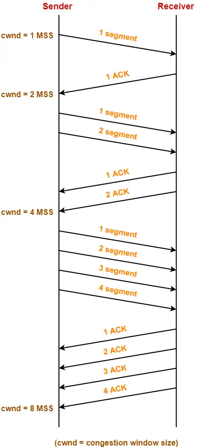
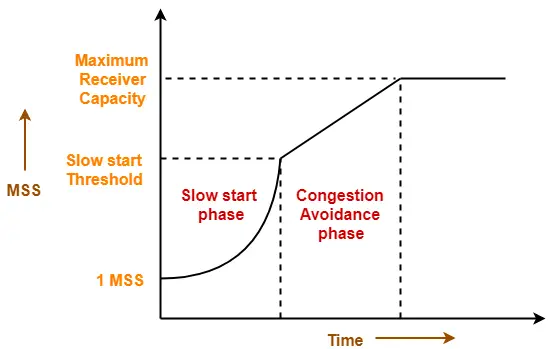
1. Slow Start Phase-


  • Initially, sender sets congestion window size = Maximum Segment Size (1 MSS).
  • After receiving each acknowledgment, sender increases the congestion window size by 1 MSS.
  • In this phase, the size of congestion window increases exponentially.


The followed formula is-


Congestion window size = Congestion window size + Maximum segment size


This is shown below-


  • After 1 round trip time, congestion window size = (2)1 = 2 MSS
  • After 2 round trip time, congestion window size = (2)2 = 4 MSS
  • After 3 round trip time, congestion window size = (2)3 = 8 MSS and so on.


This phase continues until the congestion window size reaches the slow start threshold.


Threshold

= Maximum number of TCP segments that receiver window can accommodate / 2

= (Receiver window size / Maximum Segment Size) / 2


2. Congestion Avoidance Phase-


After reaching the threshold,

  • Sender increases the congestion window size linearly to avoid the congestion.
  • On receiving each acknowledgement, sender increments the congestion window size by 1.


The followed formula is-


Congestion window size = Congestion window size + 1


This phase continues until the congestion window size becomes equal to the receiver window size.


3. Congestion Detection Phase-


When sender detects the loss of segments, it reacts in different ways depending on how the loss is detected-


Case-01: Detection On Time Out-


  • Time Out Timer expires before receiving the acknowledgement for a segment.
  • This case suggests the stronger possibility of congestion in the network.
  • There are chances that a segment has been dropped in the network.


Reaction-


In this case, sender reacts by-

  • Setting the slow start threshold to half of the current congestion window size.
  • Decreasing the congestion window size to 1 MSS.
  • Resuming the slow start phase.


Case-02: Detection On Receiving 3 Duplicate Acknowledgements-


  • Sender receives 3 duplicate acknowledgements for a segment.
  • This case suggests the weaker possibility of congestion in the network.
  • There are chances that a segment has been dropped but few segments sent later may have reached.


Reaction-


In this case, sender reacts by-

  • Setting the slow start threshold to half of the current congestion window size.
  • Decreasing the congestion window size to slow start threshold.
  • Resuming the congestion avoidance phase.


Next Article- Practice Problems On TCP Congestion Control


Get more notes and other study material of Computer Networks.

Watch video lectures by visiting our YouTube channel LearnVidFun.
TCP Header | TCP Header Format | TCP Flags

Transmission Control Protocol-


Before you go through this article, make sure that you have gone through the previous article on TCP in Networking.


We have discussed-

  • Transmission Control Protocol is a transport layer protocol.
  • It continuously receives data from the application layer.
  • It divides the data into chunks where each chunk is a collection of bytes.
  • It then creates TCP segments by adding a TCP header to the data chunks.
  • TCP segments are encapsulated in the IP datagram.


TCP segment = TCP header + Data chunk


In this article, we will discuss about TCP Header.


TCP Header-


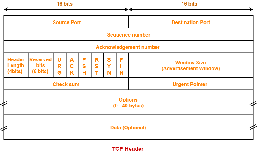
The following diagram represents the TCP header format-


Let us discuss each field of TCP header one by one.


1. Source Port-


  • Source Port is a 16 bit field.
  • It identifies the port of the sending application.


2. Destination Port-


  • Destination Port is a 16 bit field.
  • It identifies the port of the receiving application.


NOTE

It is important to note-

  • A TCP connection is uniquely identified by using-

Combination of port numbers and IP Addresses of sender and receiver

  • IP Addresses indicate which systems are communicating.
  • Port numbers indicate which end to end sockets are communicating.


3. Sequence Number-


  • Sequence number is a 32 bit field.
  • TCP assigns a unique sequence number to each byte of data contained in the TCP segment.
  • This field contains the sequence number of the first data byte.


4. Acknowledgement Number-


  • Acknowledgment number is a 32 bit field.
  • It contains sequence number of the data byte that receiver expects to receive next from the sender.
  • It is always sequence number of the last received data byte incremented by 1.


5. Header Length-


  • Header length is a 4 bit field.
  • It contains the length of TCP header.
  • It helps in knowing from where the actual data begins.


Minimum and Maximum Header length-


The length of TCP header always lies in the range-

[20 bytes , 60 bytes]


  • The initial 5 rows of the TCP header are always used.
  • So, minimum length of TCP header = 5 x 4 bytes = 20 bytes.
  • The size of the 6th row representing the Options field vary.
  • The size of Options field can go up to 40 bytes.
  • So, maximum length of TCP header = 20 bytes + 40 bytes = 60 bytes.


Concept of Scaling Factor-


  • Header length is a 4 bit field.
  • So, the range of decimal values that can be represented is [0, 15].
  • But the range of header length is [20, 60].
  • So, to represent the header length, we use a scaling factor of 4.


In general,


Header length = Header length field value x 4 bytes


Examples-


  • If header length field contains decimal value 5 (represented as 0101), then-

Header length = 5 x 4 = 20 bytes

  • If header length field contains decimal value 10 (represented as 1010), then-

Header length = 10 x 4 = 40 bytes

  • If header length field contains decimal value 15 (represented as 1111), then-

Header length = 15 x 4 = 60 bytes


NOTES

It is important to note-

  • Header length and Header length field value are two different things.
  • The range of header length field value is always [5, 15].
  • The range of header length is always [20, 60].


While solving questions-

  • If the given value lies in the range [5, 15] then it must be the header length field value.
  • This is because the range of header length is always [20, 60].


6. Reserved Bits-


  • The 6 bits are reserved.
  • These bits are not used.


7. URG Bit-


URG bit is used to treat certain data on an urgent basis.


When URG bit is set to 1,

  • It indicates the receiver that certain amount of data within the current segment is urgent.
  • Urgent data is pointed out by evaluating the urgent pointer field.
  • The urgent data has be prioritized.
  • Receiver forwards urgent data to the receiving application on a separate channel.


8. ACK Bit-


ACK bit indicates whether acknowledgement number field is valid or not.


  • When ACK bit is set to 1, it indicates that acknowledgement number contained in the TCP header is valid.
  • For all TCP segments except request segment, ACK bit is set to 1.
  • Request segment is sent for connection establishment during Three Way Handshake.


9. PSH Bit-


PSH bit is used to push the entire buffer immediately to the receiving application.


When PSH bit is set to 1,

  • All the segments in the buffer are immediately pushed to the receiving application.
  • No wait is done for filling the entire buffer.
  • This makes the entire buffer to free up immediately.


NOTE

It is important to note-

  • Unlike URG bit, PSH bit does not prioritize the data.
  • It just causes all the segments in the buffer to be pushed immediately to the receiving application.
  • The same order is maintained in which the segments arrived.
  • It is not a good practice to set PSH bit = 1.
  • This is because it disrupts the working of receiver’s CPU and forces it to take an action immediately.


10. RST Bit-


RST bit is used to reset the TCP connection.


When RST bit is set to 1,

  • It indicates the receiver to terminate the connection immediately.
  • It causes both the sides to release the connection and all its resources abnormally.
  • The transfer of data ceases in both the directions.
  • It may result in the loss of data that is in transit.


This is used only when-

  • There are unrecoverable errors.
  • There is no chance of terminating the TCP connection normally.


11. SYN Bit-


SYN bit is used to synchronize the sequence numbers.


When SYN bit is set to 1,

  • It indicates the receiver that the sequence number contained in the TCP header is the initial sequence number.
  • Request segment sent for connection establishment during Three way handshake contains SYN bit set to 1.


12. FIN Bit-


FIN bit is used to terminate the TCP connection.


When FIN bit is set to 1,

  • It indicates the receiver that the sender wants to terminate the connection.
  • FIN segment sent for TCP Connection Termination contains FIN bit set to 1.


13. Window Size-


  • Window size is a 16 bit field.
  • It contains the size of the receiving window of the sender.
  • It advertises how much data (in bytes) the sender can receive without acknowledgement.
  • Thus, window size is used for Flow Control.


NOTE

It is important to note-

  • The window size changes dynamically during data transmission.
  • It usually increases during TCP transmission up to a point where congestion is detected.
  • After congestion is detected, the window size is reduced to avoid having to drop packets.


14. Checksum-


  • Checksum is a 16 bit field used for error control.
  • It verifies the integrity of data in the TCP payload.
  • Sender adds CRC checksum to the checksum field before sending the data.
  • Receiver rejects the data that fails the CRC check.


Also Read- CRC | Checksum


15. Urgent Pointer-


  • Urgent pointer is a 16 bit field.
  • It indicates how much data in the current segment counting from the first data byte is urgent.
  • Urgent pointer added to the sequence number indicates the end of urgent data byte.
  • This field is considered valid and evaluated only if the URG bit is set to 1.


USEFUL FORMULAS


Formula-01:

Number of urgent bytes = Urgent pointer + 1


Formula-02:

End of urgent byte

= Sequence number of the first byte in the segment + Urgent pointer


16. Options-


  • Options field is used for several purposes.
  • The size of options field vary from 0 bytes to 40 bytes.


Options field is generally used for the following purposes-

  1. Time stamp
  2. Window size extension
  3. Parameter negotiation
  4. Padding


A. Time Stamp-


When wrap around time is less than life time of a segment,

  • Multiple segments having the same sequence number may appear at the receiver side.
  • This makes it difficult for the receiver to identify the correct segment.
  • If time stamp is used, it marks the age of TCP segments.
  • Based on the time stamp, receiver can identify the correct segment.


B. Window Size Extension-


  • Options field may be used to represent a window size greater than 16 bits.
  • Using window size field of TCP header, window size of only 16 bits can be represented.
  • If the receiver wants to receive more data, it can advertise its greater window size using this field.
  • The extra bits are then appended in Options field.


C. Parameter Negotiation-


Options field is used for parameters negotiation.

Example- During connection establishment,

  • Both sender and receiver have to specify their maximum segment size.
  • To specify maximum segment size, there is no special field.
  • So, they specify their maximum segment size using this field and negotiates.


D. Padding-


  • Addition of dummy data to fill up unused space in the transmission unit and make it conform to the standard size is called as padding.
  • Options field is used for padding.


Example-


  • When header length is not a multiple of 4, extra zeroes are padded in the Options field.
  • By doing so, header length becomes a multiple of 4.
  • If header length = 30 bytes, 2 bytes of dummy data is added to the header.
  • This makes header length = 32 bytes.
  • Then, the value 32 / 4 = 8 is put in the header length field.
  • In worst case, 3 bytes of dummy data might have to be padded to make the header length a multiple of 4.


Also Read- IPv4 Header | UDP Header


To gain better understanding about TCP Header,

Watch this Video Lecture


Next Article- TCP Sequence Number | Wrap Around Time


Get more notes and other study material of Computer Networks.

Watch video lectures by visiting our YouTube channel LearnVidFun.