Tag: Process Management in Operating System

SJF Scheduling | SRTF | CPU Scheduling

SJF Scheduling-


In SJF Scheduling,

  • Out of all the available processes, CPU is assigned to the process having smallest burst time.
  • In case of a tie, it is broken by FCFS Scheduling.


  • SJF Scheduling can be used in both preemptive and non-preemptive mode.
  • Preemptive mode of Shortest Job First is called as Shortest Remaining Time First (SRTF).


Advantages-


  • SRTF is optimal and guarantees the minimum average waiting time.
  • It provides a standard for other algorithms since no other algorithm performs better than it.


Disadvantages-


  • It can not be implemented practically since burst time of the processes can not be known in advance.
  • It leads to starvation for processes with larger burst time.
  • Priorities can not be set for the processes.
  • Processes with larger burst time have poor response time.


PRACTICE PROBLEMS BASED ON SJF SCHEDULING-


Problem-01:


Consider the set of 5 processes whose arrival time and burst time are given below-


Process Id Arrival time Burst time
P1 3 1
P2 1 4
P3 4 2
P4 0 6
P5 2 3


If the CPU scheduling policy is SJF non-preemptive, calculate the average waiting time and average turn around time.


Solution-


Gantt Chart-


Now, we know-

  • Turn Around time = Exit time – Arrival time
  • Waiting time = Turn Around time – Burst time


Also read- Various Times of Process


Process Id Exit time Turn Around time Waiting time
P1 7 7 – 3 = 4 4 – 1 = 3
P2 16 16 – 1 = 15 15 – 4 = 11
P3 9 9 – 4 = 5 5 – 2 = 3
P4 6 6 – 0 = 6 6 – 6 = 0
P5 12 12 – 2 = 10 10 – 3 = 7


Now,

  • Average Turn Around time = (4 + 15 + 5 + 6 + 10) / 5 = 40 / 5 = 8 unit
  • Average waiting time = (3 + 11 + 3 + 0 + 7) / 5 = 24 / 5 = 4.8 unit


Problem-02:


Consider the set of 5 processes whose arrival time and burst time are given below-


Process Id Arrival time Burst time
P1 3 1
P2 1 4
P3 4 2
P4 0 6
P5 2 3


If the CPU scheduling policy is SJF preemptive, calculate the average waiting time and average turn around time.


Solution-


Gantt Chart-


Now, we know-

  • Turn Around time = Exit time – Arrival time
  • Waiting time = Turn Around time – Burst time


Process Id Exit time Turn Around time Waiting time
P1 4 4 – 3 = 1 1 – 1 = 0
P2 6 6 – 1 = 5 5 – 4 = 1
P3 8 8 – 4 = 4 4 – 2 = 2
P4 16 16 – 0 = 16 16 – 6 = 10
P5 11 11 – 2 = 9 9 – 3 = 6


Now,

  • Average Turn Around time = (1 + 5 + 4 + 16 + 9) / 5 = 35 / 5 = 7 unit
  • Average waiting time = (0 + 1 + 2 + 10 + 6) / 5 = 19 / 5 = 3.8 unit


Problem-03:


Consider the set of 6 processes whose arrival time and burst time are given below-


Process Id Arrival time Burst time
P1 0 7
P2 1 5
P3 2 3
P4 3 1
P5 4 2
P6 5 1


If the CPU scheduling policy is shortest remaining time first, calculate the average waiting time and average turn around time.


Solution-


Gantt Chart-


Now, we know-

  • Turn Around time = Exit time – Arrival time
  • Waiting time = Turn Around time – Burst time


Process Id Exit time Turn Around time Waiting time
P1 19 19 – 0 = 19 19 – 7 = 12
P2 13 13 – 1 = 12 12 – 5 = 7
P3 6 6 – 2 = 4 4 – 3 = 1
P4 4 4 – 3 = 1 1 – 1 = 0
P5 9 9 – 4 = 5 5 – 2 = 3
P6 7 7 – 5 = 2 2 – 1 = 1


Now,

  • Average Turn Around time = (19 + 12 + 4 + 1 + 5 + 2) / 6 = 43 / 6 = 7.17 unit
  • Average waiting time = (12 + 7 + 1 + 0 + 3 + 1) / 6 = 24 / 6 = 4 unit


Problem-04:


Consider the set of 3 processes whose arrival time and burst time are given below-


Process Id Arrival time Burst time
P1 0 9
P2 1 4
P3 2 9


If the CPU scheduling policy is SRTF, calculate the average waiting time and average turn around time.


Solution-


Gantt Chart-


Now, we know-

  • Turn Around time = Exit time – Arrival time
  • Waiting time = Turn Around time – Burst time


Process Id Exit time Turn Around time Waiting time
P1 13 13 – 0 = 13 13 – 9 = 4
P2 5 5 – 1 = 4 4 – 4 = 0
P3 22 22- 2 = 20 20 – 9 = 11


Now,

  • Average Turn Around time = (13 + 4 + 20) / 3 = 37 / 3 = 12.33 unit
  • Average waiting time = (4 + 0 + 11) / 3 = 15 / 3 = 5 unit


Problem-05:


Consider the set of 4 processes whose arrival time and burst time are given below-


Process Id Arrival time Burst time
P1 0 20
P2 15 25
P3 30 10
P4 45 15


If the CPU scheduling policy is SRTF, calculate the waiting time of process P2.


Solution-


Gantt Chart-


Now, we know-

  • Turn Around time = Exit time – Arrival time
  • Waiting time = Turn Around time – Burst time


Thus,

  • Turn Around Time of process P2 = 55 – 15 = 40 unit
  • Waiting time of process P2 = 40 – 25 = 15 unit


Implementation of Algorithm-


  • Practically, the algorithm can not be implemented but theoretically it can be implemented.
  • Among all the available processes, the process with smallest burst time has to be selected.
  • Min heap is a suitable data structure where root element contains the process with least burst time.
  • In min heap, each process will be added and deleted exactly once.
  • Adding an element takes log(n) time and deleting an element takes log(n) time.
  • Thus, for n processes, time complexity = n x 2log(n) = nlog(n)


To gain better understanding about SJF Scheduling,

Watch this Video Lecture


Next Article- Techniques to Predict Burst Time


Get more notes and other study material of Operating System.

Watch video lectures by visiting our YouTube channel LearnVidFun.

First Come First Serve | CPU Scheduling

FCFS Scheduling-


In FCFS Scheduling,

  • The process which arrives first in the ready queue is firstly assigned the CPU.
  • In case of a tie, process with smaller process id is executed first.
  • It is always non-preemptive in nature.


Advantages-


  • It is simple and easy to understand.
  • It can be easily implemented using queue data structure.
  • It does not lead to starvation.


Disadvantages-


  • It does not consider the priority or burst time of the processes.
  • It suffers from convoy effect.


Convoy Effect

In convoy effect,

  • Consider processes with higher burst time arrived before the processes with smaller burst time.
  • Then, smaller processes have to wait for a long time for longer processes to release the CPU.


PRACTICE PROBLEMS BASED ON FCFS SCHEDULING-


Problem-01:


Consider the set of 5 processes whose arrival time and burst time are given below-


Process Id Arrival time Burst time
P1 3 4
P2 5 3
P3 0 2
P4 5 1
P5 4 3


If the CPU scheduling policy is FCFS, calculate the average waiting time and average turn around time.


Solution-


Gantt Chart-


Here, black box represents the idle time of CPU.


Now, we know-

  • Turn Around time = Exit time – Arrival time
  • Waiting time = Turn Around time – Burst time


Also read- Various Times of Process


Process Id Exit time Turn Around time Waiting time
P1 7 7 – 3 = 4 4 – 4 = 0
P2 13 13 – 5 = 8 8 – 3 = 5
P3 2 2 – 0 = 2 2 – 2 = 0
P4 14 14 – 5 = 9 9 – 1 = 8
P5 10 10 – 4 = 6 6 – 3 = 3


Now,

  • Average Turn Around time = (4 + 8 + 2 + 9 + 6) / 5 = 29 / 5 = 5.8 unit
  • Average waiting time = (0 + 5 + 0 + 8 + 3) / 5 = 16 / 5 = 3.2 unit


Problem-02:


Consider the set of 3 processes whose arrival time and burst time are given below-


Process Id Arrival time Burst time
P1 0 2
P2 3 1
P3 5 6


If the CPU scheduling policy is FCFS, calculate the average waiting time and average turn around time.


Solution-


Gantt Chart-


Here, black box represents the idle time of CPU.


Now, we know-

  • Turn Around time = Exit time – Arrival time
  • Waiting time = Turn Around time – Burst time


Process Id Exit time Turn Around time Waiting time
P1 2 2 – 0 = 2 2 – 2 = 0
P2 4 4 – 3 = 1 1 – 1 = 0
P3 11 11- 5 = 6 6 – 6 = 0


Now,

  • Average Turn Around time = (2 + 1 + 6) / 3 = 9 / 3 = 3 unit
  • Average waiting time = (0 + 0 + 0) / 3 = 0 / 3 = 0 unit


Problem-03:


Consider the set of 6 processes whose arrival time and burst time are given below-


Process Id Arrival time Burst time
P1 0 3
P2 1 2
P3 2 1
P4 3 4
P5 4 5
P6 5 2


If the CPU scheduling policy is FCFS and there is 1 unit of overhead in scheduling the processes, find the efficiency of the algorithm.


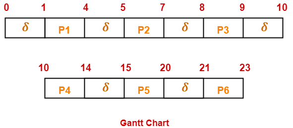
Solution-


Gantt Chart-


Here, δ denotes the context switching overhead.


Now,

  • Useless time / Wasted time = 6 x δ = 6 x 1 = 6 unit
  • Total time = 23 unit
  • Useful time = 23 unit – 6 unit = 17 unit


Efficiency (η)

= Useful time  / Total Total

= 17 unit / 23 unit

= 0.7391

= 73.91%


To gain better understanding about FCFS Scheduling,

Watch this Video


Next Article- SJF Scheduling | SRTF Scheduling


Get more notes and other study material of Operating System.

Watch video lectures by visiting our YouTube channel LearnVidFun.

Turn Around Time | Response Time | Waiting Time

Various Times Related To Process-


Before you go through this article, make sure that you have gone through the previous article on Process States.


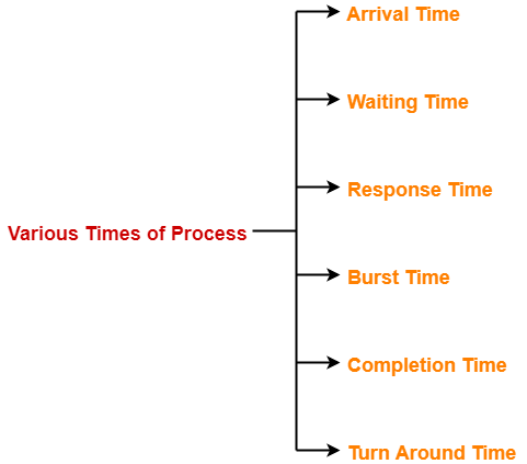
Various times related to process are-


  1. Arrival time
  2. Waiting time
  3. Response time
  4. Burst time
  5. Completion time
  6. Turn Around Time


1. Arrival Time-


  • Arrival time is the point of time at which a process enters the ready queue.


2. Waiting Time-


  • Waiting time is the amount of time spent by a process waiting in the ready queue for getting the CPU.


Waiting time = Turn Around time – Burst time


3. Response Time-


  • Response time is the amount of time after which a process gets the CPU for the first time after entering the ready queue.


Response Time = Time at which process first gets the CPU – Arrival time


4. Burst Time-


  • Burst time is the amount of time required by a process for executing on CPU.
  • It is also called as execution time or running time.
  • Burst time of a process can not be known in advance before executing the process.
  • It can be known only after the process has executed.


5. Completion Time-


  • Completion time is the point of time at which a process completes its execution on the CPU and takes exit from the system.
  • It is also called as exit time.


6. Turn Around Time-


  • Turn Around time is the total amount of time spent by a process in the system.
  • When present in the system, a process is either waiting in the ready queue for getting the CPU or it is executing on the CPU.


Turn Around time = Burst time + Waiting time

OR

Turn Around time = Completion time – Arrival time


Important Note-


While discussing the above definitions,

  • We have considered that the process does not require an I/O operation.
  • When process is present in the system, it will be either waiting for the CPU in the ready state or it will be executing on the CPU.


To gain better understanding about various times of process,

Watch this Video Lecture


Next Article- FCFS Algorithm | CPU Scheduling


Get more notes and other study material of Operating System.

Watch video lectures by visiting our YouTube channel LearnVidFun.
CPU Schedulers | Schedulers in OS | Schedulers

Schedulers in OS-


  • Schedulers in OS are special system software.
  • They help in scheduling the processes in various ways.
  • They are mainly responsible for selecting the jobs to be submitted into the system and deciding which process to run.


Types of Schedulers-


There are 3 kinds of schedulers-


  1. Long-term scheduler
  2. Short-term scheduler
  3. Medium-term scheduler


1. Long-term Scheduler-


The primary objective of long-term scheduler is to maintain a good degree of multiprogramming.


  • Long-term scheduler is also known as Job Scheduler.
  • It selects a balanced mix of I/O bound and CPU bound processes from the secondary memory (new state).
  • Then, it loads the selected processes into the main memory (ready state) for execution.


2. Short-term Scheduler-


The primary objective of short-term scheduler is to increase the system performance.


  • Short-term scheduler is also known as CPU Scheduler.
  • It decides which process to execute next from the ready queue.
  • After short-term scheduler decides the process, Dispatcher assigns the decided process to the CPU for execution.


3. Medium-term Scheduler-


The primary objective of medium-term scheduler is to perform swapping.


  • Medium-term scheduler swaps-out the processes from main memory to secondary memory to free up the main memory when required.
  • Thus, medium-term scheduler reduces the degree of multiprogramming.
  • After some time when main memory becomes available, medium-term scheduler swaps-in the swapped-out process to the main memory and its execution is resumed from where it left off.
  • Swapping may also be required to improve the process mix.


Comparison Of Schedulers-


Long-term scheduler Medium-term scheduler Short-term scheduler
It is a job scheduler It is a process swapping scheduler. It is a CPU scheduler
It controls the degree of multiprogramming. It reduces the degree of multiprogramming. It provides lesser control over degree of multiprogramming.
Speed is lesser than short-term scheduler Speed is in between the long-term and short-term schedulers. Speed is fastest among the other two.
It is minimal or almost absent in time sharing system. It is a part of time sharing system. It is also minimal in time sharing system.
It selects processes from new state and loads them into ready state. It swaps-out processes from main memory to secondary memory and later swaps in. It selects processes from the ready state and assigns to the CPU.
Operates less frequently since processes are not rapidly created. Operates more frequently than long-term scheduler but less frequently than short-term scheduler. Operates very frequently to match the speed of CPU since CPU rapidly switches from one process to another


Degree of Multiprogramming-


In multiprogramming systems,

  • Multiple processes may be present in the ready state which are all ready for execution.
  • Degree of multiprogramming is the maximum number of processes that can be present in the ready state.
  • Long-term scheduler controls the degree of multiprogramming.
  • Medium-term scheduler reduces the degree of multiprogramming.


Optimal Degree of Multiprogramming-


  • An optimal degree of multiprogramming means average rate of process creation is equal to the average departure rate of processes from main memory.
  • It is the responsibility of long-term scheduler to maintain a good degree of multiprogramming.


To gain better understanding about Schedulers in OS,

Watch this Video Lecture


Next Article- Various Times Of Process


Get more notes and other study material of Operating System.

Watch video lectures by visiting our YouTube channel LearnVidFun.
Process Control Block | Process Attributes

Process Control Block-


  • Process Control Block (PCB) is a data structure that stores information about a particular process.
  • This information is required by the CPU while executing the process.


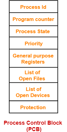
The Process Control Block of a process looks like-


  • Each process is identified by its own process control block (PCB).
  • It is also called as context of the process.


Process Attributes-


The various attributes of process stored in the PCB are-


1. Process Id-


  • Process Id is a unique Id that identifies each process of the system uniquely.
  • A process Id is assigned to each process during its creation.


2. Program Counter-


  • Program counter specifies the address of the instruction to be executed next.
  • Before execution, program counter is initialized with the address of the first instruction of the program.
  • After executing an instruction, value of program counter is automatically incremented to point to the next instruction.
  • This process repeats till the end of the program.


3. Process State-


  • Each process goes through different states during its lifetime.
  • Process state specifies the current state of the process.


Read more- Process States in OS


4. Priority-


  • Priority specifies how urgent is to execute the process.
  • Process with the highest priority is allocated the CPU first among all the processes.


5. General Purpose Registers-


  • General purpose registers are used to hold the data of process generated during its execution.
  • Each process has its own set of registers which are maintained by its PCB.


6. List of Open Files-


  • Each process requires some files which must be present in the main memory during its execution.
  • PCB maintains a list of files used by the process during its execution.


7. List of Open Devices-


  • PCB maintains a list of open devices used by the process during its execution.


Important Notes-


  • PCB of each process resides in the main memory.
  • There exists only one PCB corresponding to each process.
  • PCB of all the processes are present in a linked list.


To gain better understanding about Process Control Block,

Watch this Video Lecture


Next Article- Schedulers in OS


Get more notes and other study material of Operating System.

Watch video lectures by visiting our YouTube channel LearnVidFun.