Tag: Digital Logic Design Notes

Universal Logic Gates | NAND Gate | NOR Gate

Logic Gates-


Before you go through this article, make sure that you have gone through the previous article on Logic Gates.


We have discussed-

  • Logic gates are the basic building blocks of any digital circuit.
  • There are 3 basic logic gates- AND, NOT, OR.
  • Logic gates are classified as-


In this article, we will discuss about Universal Logic Gates.


Universal Logic Gates-


Universal logic gates are the logic gates that are capable of implementing any Boolean function

without requiring any other type of gate.


They are called as “Universal Gates” because-

  • They can realize all the binary operations.
  • All the basic logic gates can be derived from them.


They have the following properties-

  • Universal gates are not associative in nature.
  • Universal gates are commutative in nature.


There are following two universal logic gates-


  1. NAND Gate
  2. NOR Gate


1. NAND Gate-


  • A NAND Gate is constructed by connecting a NOT Gate at the output terminal of the AND Gate.
  • The output of NAND gate is high (‘1’) if at least one of its inputs is low (‘0’).
  • The output of NAND gate is low (‘0’) if all of its inputs are high (‘1’).


Logic Symbol-


The logic symbol for NAND Gate is as shown below-


Truth Table-


The truth table for NAND Gate is as shown below-


A B Y = (A.B)’
0 0 1
0 1 1
1 0 1
1 1 0

Truth Table


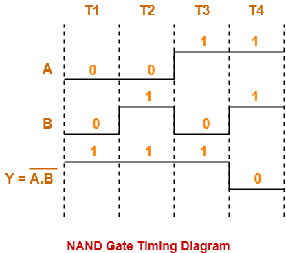
Timing Diagram-


The timing diagram for NAND Gate is as shown below-


2. NOR Gate-


  • A NOR Gate is constructed by connecting a NOT Gate at the output terminal of the OR Gate.
  • The output of OR gate is high (‘1’) if all of its inputs are low (‘0’).
  • The output of OR gate is low (‘0’) if any of its inputs is high (‘1’).


Logic Symbol-


The logic symbol for NOR Gate is as shown below-


Truth Table-


The truth table for NOR Gate is as shown below-


A B Y = A + B
0 0 1
0 1 0
1 0 0
1 1 0

Truth Table


Timing Diagram-


The timing diagram for NOR Gate is as shown below-


To gain better understanding about Universal Logic Gates,

Watch this Video Lecture


Next Article- Alternative Logic Gates


Get more notes and other study material of Digital Design.

Watch video lectures by visiting our YouTube channel LearnVidFun.

Logic Gates | Definitions | Types | Symbols | Truth Tables

Logic Gates-


Logic Gates may be defined as-


Logic gates are the digital circuits capable of performing a particular logic function

by operating on a number of binary inputs.

OR

Logic gates are the basic building blocks of any digital circuit.


Types Of Logic Gates-


Logic gates can be broadly classified as-


In this article, we will discuss about Basic Logic Gates.


Basic Logic Gates-


Basic Logic Gates are the fundamental logic gates using which universal logic gates and other logic gates are constructed.


They have the following properties-

  • Basic logic gates are associative in nature.
  • Basic logic gates are commutative in nature.


There are following three basic logic gates-

  1. AND Gate
  2. OR Gate
  3. NOT Gate


1. AND Gate-


  • The output of AND gate is high (‘1’) if all of its inputs are high (‘1’).
  • The output of AND gate is low (‘0’) if any one of its inputs is low (‘0’).


Logic Symbol-


The logic symbol for AND Gate is as shown below-


Truth Table-


The truth table for AND Gate is as shown below-


A B Y = A.B
0 0 0
0 1 0
1 0 0
1 1 1

Truth Table


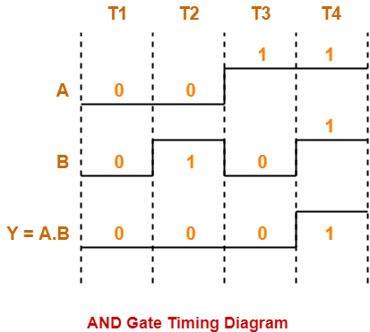
Timing Diagram-


The timing diagram for AND Gate is as shown below-


2. OR Gate-


  • The output of OR gate is high (‘1’) if any one of its inputs is high (‘1’).
  • The output of OR gate is low (‘0’) if all of its inputs are low (‘0’).


Logic Symbol-


The logic symbol for OR Gate is as shown below-


Truth Table-


The truth table for OR Gate is as shown below-


A B Y = A + B
0 0 0
0 1 1
1 0 1
1 1 1

Truth Table


Timing Diagram-


The timing diagram for OR Gate is as shown below-


Also Read- Alternative Logic Gates


3. NOT Gate-


  • The output of NOT gate is high (‘1’) if its input is low (‘0’).
  • The output of NOT gate is low (‘0’) if its input is high (‘1’).


From here-

  • It is clear that NOT gate simply inverts the given input.
  • Since NOT gate simply inverts the given input, therefore it is also known as Inverter Gate.


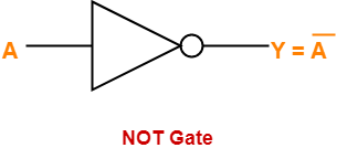
Logic Symbol-


The logic symbol for NOT Gate is as shown below-


Truth Table-


The truth table for NOT Gate is as shown below-


A Y = A’
0 1
1 0

Truth Table


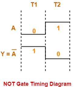
Timing Diagram-


The timing diagram for NOT Gate is as shown below-


To gain better understanding about Logic Gates,

Watch this Video Lecture


Next Article- Universal Logic Gates


Get more notes and other study material of Digital Design.

Watch video lectures by visiting our YouTube channel LearnVidFun.

Delay in Ripple Carry Adder | Ripple Carry Adder

Ripple Carry Adder-


Before you go through this article, make sure that you have gone through the previous article on Ripple Carry Adder.


We have discussed-

  • Ripple Carry Adder is a combinational logic circuit.
  • It is used for the purpose of adding two n-bit binary numbers.
  • It is also called as n-bit parallel adder.


In this article, we will discuss about Delay in Ripple Carry Adder.


Delay in Ripple Carry Adder-


Consider a N-bit Ripple Carry Adder as shown-
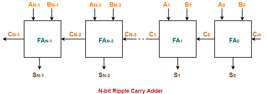


The following kinds of problems may be asked based on delay calculation in Ripple Carry Adder.


Type-01 Problem:


  • You will be given the carry propagation delay and sum propagation delay of each full adder.
  • You will be asked to calculate the worst case delay of the ripple carry adder.


Solution-


Know These Terms?


It is important to know the following terms-

  • Carry propagation delay of a full adder is the time taken by it to produce the output carry bit.
  • Sum propagation delay of a full adder is the time taken by it to produce the output sum bit.
  • Worst case delay of a ripple carry adder is the time after which the output sum bit and carry bit becomes available from the last full adder.


In Ripple Carry Adder,

  • A full adder becomes active only when its carry in is made available by its adjacent less significant full adder.
  • When carry in becomes available to the full adder, it starts its operation.
  • It produces the corresponding output sum bit and carry bit.


If you are asked to calculate the time after which the output sum bit or carry bit becomes available from any particular full adder, then it is calculated as-


Time After Which Carry Bit Cx Becomes Available-


Required time

= Total number of full adders till full adder producing Cx X Carry propagation delay of full adder


Time After Which Sum Bit Sx Becomes Available-


Required time

= Time taken for its carry in to become available + Sum propagation delay of full adder

= { Total number of full adders before full adder producing Sx X Carry propagation delay of full adder } + Sum propagation delay of full adder


We will calculate worst case delay for the last full adder.


Also Read- Full Adder


Type-02 Problem:


  • You will be given the propagation delay of some basic logic gates.
  • You will be told how the full adder has been implemented.
  • Then, you will be asked to calculate the worst case delay of Ripple Carry Adder.


Suppose each full adder in the given ripple carry adder has been implemented as-
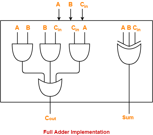


Solution-


  • The computation has to be done in the same manner as in Type-01 problem.
  • It’s just that in Type-02 problem, one step is increased.
  • We have to first calculate the carry propagation delay and sum propagation delay in terms of logic gates.
  • Then, our problem will reduce to Type-01 problem.


Let-

  • Propagation delay of AND gate = Tpd (AND)
  • Propagation delay of OR gate = Tpd (OR)
  • Propagation delay of XOR gate = Tpd (XOR)


Calculating Carry Propagation Delay-


  • We calculate the carry propagation delay of full adder using its carry generator logic circuit.
  • It has 2 levels in the given implementation.
  • At first level, three AND gates operate.
  • All the three AND gates operate in parallel.
  • So, we consider the propagation delay due to only one AND gate.
  • At second level, OR gate operates.


Now,

Carry propagation delay of full adder

= Time taken by it to generate the output carry bit

= Propagation delay of AND gate + Propagation delay of OR gate

= Tpd (AND) + Tpd (OR)


Calculating Sum Propagation Delay-


  • We calculate the sum propagation delay of full adder using its sum generator logic circuit.
  • It has only 1 level at which XOR gate operates in the given implementation.


Now,

Sum propagation delay of full adder

=  Time taken by it to generate the output sum bit

= Propagation delay of XOR gate

= Tpd (XOR)


Now,

  • We have got the carry propagation delay and sum propagation delay of full adders.
  • Our problem reduces to Type-01 problem.
  • We use the same formulas as we have learnt in Type-01 problem to make the required calculations.


NOTE-


Consider in the question,

  • It was said that while implementing the sum generator logic circuit of full adders, only 2-input XOR gates are used.
  • Then, in that case we would require two such XOR gates which would work at 2 levels.
  • So, in that case, sum propagation delay would be twice the propagation delay of XOR gate.


PRACTICE PROBLEMS BASED ON RIPPLE CARRY ADDER DELAY CALCULATION-


Problem-01:


A 16-bit ripple carry adder is realized using 16 identical full adders. The carry propagation delay of each full adder is 12 ns and the sum propagation delay of each full adder is 15 ns. The worst case delay of this 16 bit adder will be ______?

A) 195 ns

B) 220 ns

C) 250 ns

D) 300 ns


Solution-


We consider the last full adder for worst case delay.


Time after which output carry bit becomes available from the last full adder

= Total number of full adders X Carry propagation delay of full adder

= 16 x 12 ns

= 192 ns


Time after which output sum bit becomes available from the last full adder

= Time taken for its carry in to become available + Sum propagation delay of full adder

= { Total number of full adders before last full adder X Carry propagation delay of full adder } + Sum propagation delay of full adder

= { 15 x 12 ns } + 15 ns

= 195 ns


Thus, Option (A) is correct.


For more explanation, Watch this Video Solution.


Problem-02:


Following figure shows the implementation of full adders in a 16-bit ripple carry adder realized using 16 identical full adders. The propagation delay of the XOR, AND and OR gates are 20 ns, 15 ns and 10 ns respectively. The worst case delay of this 16 bit adder will be ______?

A) 395 ns

B) 220 ns

C) 400 ns

D) 300 ns


Solution-


We consider the last full adder for worst case delay.


Time after which output carry bit becomes available from the last full adder

= Total number of full adders X Carry propagation delay of full adder

= Total number of full adders X { Propagation delay of AND gate + Propagation delay of OR gate }

= 16 x { 15 ns + 10 ns }

= 16 x 25 ns

= 400 ns


Time after which output sum bit becomes available from the last full adder

= Time taken for its carry in to become available + Sum propagation delay of full adder

= { Total number of full adders before last full adder X Carry propagation delay of full adder } + Propagation delay of XOR gate

= { 15 x (15 ns + 10 ns) } + 20 ns

= 395 ns


Thus, Option (C) is correct.


To gain better understanding about Delay in Ripple Carry Adder,

Watch this Video Lecture


Next Article- Carry Look Ahead Adder


Get more notes and other study material of Digital Design.

Watch video lectures by visiting our YouTube channel LearnVidFun.
Ripple Carry Adder | 4 bit Ripple Carry Adder

Ripple Carry Adder-


  • Ripple Carry Adder is a combinational logic circuit.
  • It is used for the purpose of adding two n-bit binary numbers.
  • It requires n full adders in its circuit for adding two n-bit binary numbers.
  • It is also known as n-bit parallel adder.


4-bit Ripple Carry Adder-


4-bit ripple carry adder is used for the purpose of adding two 4-bit binary numbers.


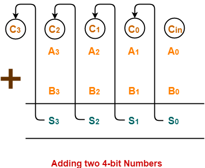
In Mathematics, any two 4-bit binary numbers A3A2A1A0 and B3B2B1B0 are added as shown below-


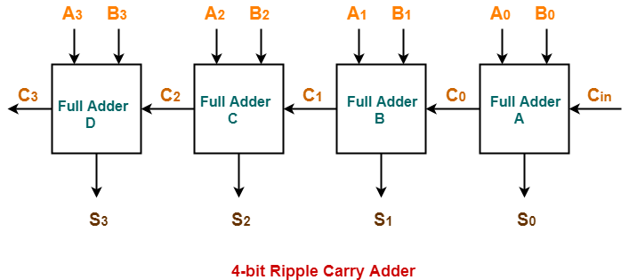
Using ripple carry adder, this addition is carried out as shown by the following logic diagram-


As shown-

  • Ripple Carry Adder works in different stages.
  • Each full adder takes the carry-in as input and produces carry-out and sum bit as output.
  • The carry-out produced by a full adder serves as carry-in for its adjacent most significant full adder.
  • When carry-in becomes available to the full adder, it activates the full adder.
  • After full adder becomes activated, it comes into operation.


Also Read- Full Adder Working


Working Of 4-bit Ripple Carry Adder-


Let-

  • The two 4-bit numbers are 0101 (A3A2A1A0) and 1010 (B3B2B1B0).
  • These numbers are to be added using a 4-bit ripple carry adder.


4-bit Ripple Carry Adder carries out the addition as explained in the following stages-


Stage-01:


  • When Cin is fed as input to the full Adder A, it activates the full adder A.
  • Then at full adder A, A0 = 1, B0 = 0, Cin = 0.


Full adder A computes the sum bit and carry bit as-


Calculation of S0


S0 = A0 ⊕  B0 ⊕ Cin

S0 = 1 ⊕ 0 ⊕ 0

S0 = 1


Calculation of C0


C0 = A0B0 ⊕  B0Cin ⊕ CinA0

C0 = 1.0 ⊕ 0.0 ⊕ 0.1

C0 = 0 ⊕ 0 ⊕ 0

C0 = 0


Stage-02:


  • When C0 is fed as input to the full adder B, it activates the full adder B.
  • Then at full adder B, A1 = 0, B1 = 1, C0 = 0.


Full adder B computes the sum bit and carry bit as-


Calculation of S1


S1 = A1 ⊕  B1 ⊕ C0

S1 = 0 ⊕ 1 ⊕ 0

S1 = 1


Calculation of C1


C1 = A1B1 ⊕  B1C0 ⊕ C0A1

C1 = 0.1 ⊕ 1.0 ⊕ 0.0

C1 = 0 ⊕ 0 ⊕ 0

C1 = 0


Stage-03:


  • When C1 is fed as input to the full adder C, it activates the full adder C.
  • Then at full adder C, A2 = 1, B2 = 0, C1 = 0.


Full adder C computes the sum bit and carry bit as-


Calculation of S2


S2 = A2 ⊕  B2 ⊕ C1

S2 = 1 ⊕ 0 ⊕ 0

S2 = 1


Calculation of C2


C2 = A2B2 ⊕  B2C1 ⊕ C1A2

C2 = 1.0 ⊕ 0.0 ⊕ 0.1

C2 = 0 ⊕ 0 ⊕ 0

C2 = 0


Stage-04:


  • When C2 is fed as input to the full adder D, it activates the full adder D.
  • Then at full adder D, A3 = 0, B3 = 1, C2 = 0.


Full adder D computes the sum bit and carry bit as-


Calculation of S3


S3 = A3 ⊕  B3 ⊕ C2

S3 = 0 ⊕ 1 ⊕ 0

S3 = 1


Calculation of C3


C3 = A3B3 ⊕  B3C2 ⊕ C2A3

C3 = 0.1 ⊕ 1.0 ⊕ 0.0

C3 = 0 ⊕ 0 ⊕ 0

C3 = 0


Thus finally,

  • Output Sum = S3S2S1S0 = 1111
  • Output Carry = C= 0


Why Ripple Carry Adder is Called So?


In Ripple Carry Adder,

  • The carry out produced by each full adder serves as carry-in for its adjacent most significant full adder.
  • Each carry bit ripples or waves into the next stage.
  • That’s why, it is called as “Ripple Carry Adder”.


Disadvantages of Ripple Carry Adder-


  • Ripple Carry Adder does not allow to use all the full adders simultaneously.
  • Each full adder has to necessarily wait until the carry bit becomes available from its adjacent full adder.
  • This increases the propagation time.
  • Due to this reason, ripple carry adder becomes extremely slow.
  • This is considered to be the biggest disadvantage of using ripple carry adder.


To overcome this disadvantage, Carry Look Ahead Adder comes into play.


To gain better understanding about Ripple Carry Adder,

Watch this Video Lecture


Next Article- Delay in Ripple Carry Adder


Get more notes and other study material of Digital Design.

Watch video lectures by visiting our YouTube channel LearnVidFun.

Full Subtractor | Definition | Circuit Diagram | Truth Table

Half Subtractor-


Before you go through this article, make sure that you have gone through the previous article on Half Subtractor.


We have discussed-

  • Half Subtractor is used for the purpose of subtracting two single bit numbers.
  • Half subtractors have no scope of taking into account “Borrow-in” from the previous circuit.
  • To overcome this drawback, full subtractor comes into play.


In this article, we will discuss about Full Subtractor.


Full Subtractor-


  • Full Subtractor is a combinational logic circuit.
  • It is used for the purpose of subtracting two single bit numbers.
  • It also takes into consideration borrow of the lower significant stage.
  • Thus, full subtractor has the ability to perform the subtraction of three bits.
  • Full subtractor contains 3 inputs and 2 outputs (Difference and Borrow) as shown-


Designing a Full Subtractor-


Full subtractor is designed in the following steps-


Step-01:


Identify the input and output variables-

  • Input variables = A, B, Bin (either 0 or 1)
  • Output variables = D, Bout where D = Difference and Bout = Borrow


Step-02:


Draw the truth table-


Inputs
Outputs
A B Bin Bout (Borrow) D (Difference)
0 0 0 0 0
0 0 1 1 1
0 1 0 1 1
0 1 1 1 0
1 0 0 0 1
1 0 1 0 0
1 1 0 0 0
1 1 1 1 1

Truth Table


Step-03:


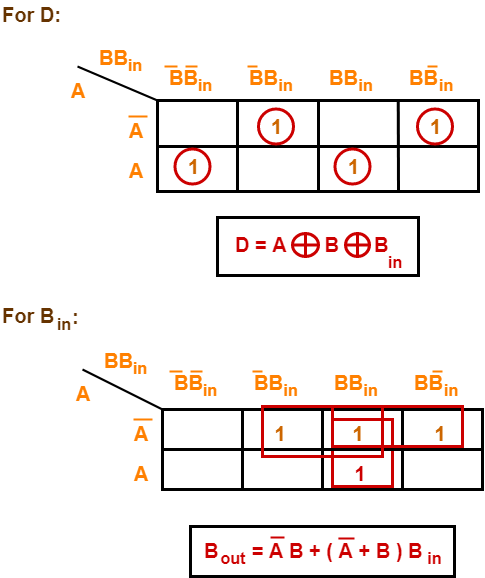
Draw K-maps using the above truth table and determine the simplified Boolean expressions-


Also Read- Full Adder


Step-04:


Draw the logic diagram.

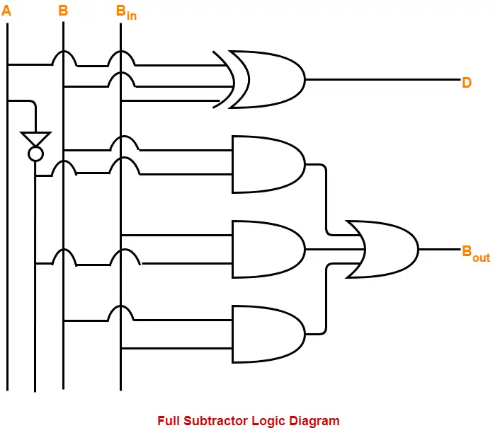
The implementation of full adder using 1 XOR gate, 3 AND gates, 1 NOT gate and 1 OR gate is as shown below-


To gain better understanding about Full Subtractor,

Watch this Video Lecture


Next Article- Ripple Carry Adder


Get more notes and other study material of Digital Design.

Watch video lectures by visiting our YouTube channel LearnVidFun.