Tag: Computer Networks

UDP Protocol | UDP Header | UDP Header Format

Transport Layer Protocols-


There are mainly two transport layer protocols that are used on the Internet-


  1. Transmission Control Protocol (TCP)
  2. User Datagram Protocol (UDP)


In this article, we will discuss about User Datagram Protocol (UDP).

Learn about Transmission Control Protocol.


UDP Protocol-


  • UDP is short for User Datagram Protocol.
  • It is the simplest transport layer protocol.
  • It has been designed to send data packets over the Internet.
  • It simply takes the datagram from the network layer, attaches its header and sends it to the user.


Characteristics of UDP-


  • It is a connectionless protocol.
  • It is a stateless protocol.
  • It is an unreliable protocol.
  • It is a fast protocol.
  • It offers the minimal transport service.
  • It is almost a null protocol.
  • It does not guarantee in order delivery.
  • It does not provide congestion control mechanism.
  • It is a good protocol for data flowing in one direction.


Need of UDP-


  • TCP proves to be an overhead for certain kinds of applications.
  • The Connection Establishment Phase, Connection Termination Phase etc of TCP are time consuming.
  • To avoid this overhead, certain applications which require fast speed and less overhead use UDP.


UDP Header-


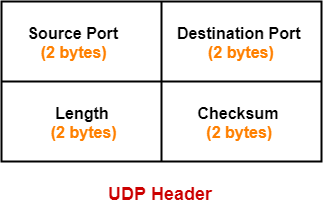
The following diagram represents the UDP Header Format-


1. Source Port-


  • Source Port is a 16 bit field.
  • It identifies the port of the sending application.


2. Destination Port-


  • Destination Port is a 16 bit field.
  • It identifies the port of the receiving application.


3. Length-


  • Length is a 16 bit field.
  • It identifies the combined length of UDP Header and Encapsulated data.


Length = Length of UDP Header + Length of encapsulated data


4. Checksum-


  • Checksum is a 16 bit field used for error control.
  • It is calculated on UDP Header, encapsulated data and IP pseudo header.
  • Checksum calculation is not mandatory in UDP.


Applications Using UDP-


Following applications use UDP-

  • Applications which require one response for one request use UDP. Example- DNS.
  • Routing Protocols like RIP and OSPF use UDP because they have very small amount of data to be transmitted.
  • Trivial File Transfer Protocol (TFTP) uses UDP to send very small sized files.
  • Broadcasting and multicasting applications use UDP.
  • Streaming applications like multimedia, video conferencing etc use UDP since they require speed over reliability.
  • Real time applications like chatting and online games use UDP.
  • Management protocols like SNMP (Simple Network Management Protocol) use UDP.
  • Bootp / DHCP uses UDP.
  • Other protocols that use UDP are- Kerberos, Network Time Protocol (NTP), Network News Protocol (NNP), Quote of the day protocol etc.


Important Notes-


Note-01:


Size of UDP Header= 8 bytes


  • Unlike TCP header, the size of UDP header is fixed.
  • This is because in UDP header, all the fields are of definite size.
  • Size of UDP Header = Sum of the size of all the fields = 8 bytes.


Note-02:


UDP is almost a null protocol.


This is because-

  • UDP provides very limited services.
  • The only services it provides are checksumming of data and multiplexing by port number.


Note-03:


UDP is an unreliable protocol.


This is because-

  • UDP does not guarantee the delivery of datagram to its respective user (application).
  • The lost datagrams are not retransmitted by UDP.


Note-04:


Checksum calculation is not mandatory in UDP.


This is because-

  • UDP is already an unreliable protocol and error checking does not make much sense.
  • Also, time is saved and transmission becomes faster by avoiding to calculate it.


It may be noted-

  • To disable the checksum, the field value is set to all 0’s.
  • If the computed checksum is zero, the field value is set to all 1’s.


Note-05:


UDP does not guarantee in order delivery.


This is because-

  • UDP allows out of order delivery to ensure better performance.
  • If some data is lost on the way, it does not call for retransmission and keeps transmitting data.


Note-06:


Application layer can perform some tasks through UDP.


Application layer can do the following tasks through UDP-

  1. Trace Route
  2. Record Route
  3. Time stamp


When required,

  • Application layer conveys to the UDP which conveys to the IP datagram.
  • UDP acts like a messenger between the application layer and the IP datagram.


Also Read- TCP Header | IPv4 Header


PRACTICE PROBLEMS BASED ON UDP HEADER-


Problem-01:


Which field is optional in UDP?

  1. Checksum
  2. Destination port
  3. Length
  4. None


Solution-


  • Checksum calculation is not mandatory in UDP.
  • Thus, Option (A) is correct.


Problem-02:


The pseudo header of IP is used in-

  1. Only TCP
  2. Only UDP
  3. Both TCP and UDP
  4. None


Solution-


  • IP Pseudo header is used in both TCP and UDP while calculating checksum.
  • Thus, Option (C) is correct.


Problem-03:


Broadcasting applications like WHOD (who daemon on UNIX) uses what transport layer protocol?

  1. TCP
  2. UDP
  3. Either TCP or UDP
  4. IGMP


Solution-


  • Broadcasting and multicasting applications use UDP.
  • Thus, Option (B) is correct.


To gain better understanding about UDP Header,

Watch this Video Lecture


Next Article- Application Layer Protocols


Get more notes and other study material of Computer Networks.

Watch video lectures by visiting our YouTube channel LearnVidFun.
CSMA CD | BackOff Algorithm | Problems

CSMA / CD Protocol-


Before you go through this article, make sure that you have gone through the previous article on CSMA / CD Protocol.


We have discussed-

  • CSMA / CD allows a station to transmit data if it senses the carrier free.
  • After undergoing collision, station waits for random back off time before transmitting again.
  • Back Off Algorithm is used to calculate back off time.


Also Read- Back Off Algorithm


In this article, we will discuss practice problems based on CSMA / CD and Back Off Algorithm.


PRACTICE PROBLEMS BASED ON CSMA / CD AND BACK OFF ALGORITHM-


Problem-01:


After the kth consecutive collision, each colliding station waits for a random time chosen from the interval-

  1. (0 to 2k) x RTT
  2. (0 to 2k-1) x RTT
  3. (0 to 2k-1) x Maximum Propagation delay
  4. (0 to 2k-1) x Maximum Propagation delay


Solution-


Clearly, Option (B) is correct.


Problem-02:


In a CSMA / CD network running at 1 Gbps over 1 km cable with no repeaters, the signal speed in the cable is 200000 km/sec. What is minimum frame size?


Solution-


Given-

  • Bandwidth = 1 Gbps
  • Distance = 1 km
  • Speed = 200000 km/sec


Calculating Propagation Delay-


Propagation delay (Tp)

= Distance / Propagation speed

= 1 km / (200000 km/sec)

= 0.5 x 10⁻⁵ sec

= 5 x 10⁻⁶ sec


Calculating Minimum Frame Size-


Minimum frame size

= 2 x Propagation delay x Bandwidth

= 2 x 5 x 10-6 sec x 109 bits per sec

= 10000 bits


Problem-03:


A 2 km long broadcast LAN has 107 bps bandwidth and uses CSMA / CD. The signal travels along the wire at 2 x 10⁸ m/sec. What is the minimum packet size that can be used on this network?

  1. 50 B
  2. 100 B
  3. 200 B
  4. None of the above


Solution-


Given-

  • Distance = 2 km
  • Bandwidth = 107 bps
  • Speed = 2 x 10⁸ m/sec


Calculating Propagation Delay-


Propagation delay (Tp)

= Distance / Propagation speed

= 2 km / (2 x 10⁸ m/sec)

= 2 x 10³ m / (2 x 10⁸ m/sec)

= 10-5 sec


Calculating Minimum Frame Size-


Minimum frame size

= 2 x Propagation delay x Bandwidth

= 2 x 10-5 sec x 107 bits per sec

= 200 bits or 25 bytes


Thus, Option (D) is correct.


Problem-04:


A and B are the only two stations on Ethernet. Each has a steady queue of frames to send. Both A and B attempts to transmit a frame, collide and A wins first back off race. At the end of this successful transmission by A, both A and B attempt to transmit and collide. The probability that A wins the second back off race is ___ .

  1. 0.5
  2. 0.625
  3. 0.75
  4. 1.0


Solution-


According to question, we have-


1st Transmission Attempt-


  • Both the stations A and B attempts to transmit a frame.
  • A collision occurs.
  • Back Off Algorithm runs.
  • Station A wins and successfully transmits its 1st data packet.


2nd Transmission Attempt-


  • Station A attempts to transmit its 2nd data packet.
  • Station B attempts to retransmit its 1st data packet.
  • A collision occurs.


Now,

  • We have been asked the probability of station A to transmit its 2nd data packet successfully after 2nd collision.
  • After the 2nd collision occurs, we have-


At Station A-


  • 2nd data packet of station A undergoes collision for the 1st time.
  • So, collision number for the 2nd data packet of station A = 1.
  • Now, station A randomly chooses a number from the range [0,21-1] = [0,1].
  • Then, station A waits for back off time and then attempts to retransmit its data packet.


At Station B-


  • 1st data packet of station B undergoes collision for the 2nd time.
  • So, collision number for the 1st data packet of station B = 2.
  • Now, station B randomly chooses a number from the range [0,22-1] = [0,3].
  • Then, station B waits for back off time and then attempts to retransmit its data packet.


Following 8 cases are possible-


Station A Station B Remark
0 0 Collision
0 1 A wins
0 2 A wins
0 3 A wins
1 0 B wins
1 1 Collision
1 2 A wins
1 3 A wins


From here,

  • Probability of A winning the 2nd back off race = 5 / 8 = 0.625.
  • Thus, Option (B) is correct.


Problem-05:


Suppose nodes A and B are on same 10 Mbps Ethernet segment and the propagation delay between two nodes is 225 bit times. Suppose A and B send frames at t=0, the frames collide then at what time, they finish transmitting a jam signal. Assume a 48 bit jam signal.


Solution-


Propagation delay (Tp)

= 225 bit times

= 225 bit / 10 Mbps

= 22.5 x 10⁻⁶ sec

= 22.5 μsec


At t = 0,


  • Nodes A and B start transmitting their frame.
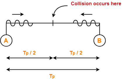
  • Since both the stations start simultaneously, so collision occurs at the mid way.
  • Time after which collision occurs = Half of propagation delay.
  • So, time after which collision occurs = 22.5 μsec / 2 = 11.25 μsec.


At t = 11.25 μsec,


  • After collision occurs at t = 11.25 μsec, collided signals start travelling back.
  • Collided signals reach the respective nodes after time = Half of propagation delay
  • Collided signals reach the respective nodes after time = 22.5 μsec / 2 = 11.25 μsec.
  • Thus, at t = 22.5 μsec, collided signals reach the respective nodes.


At t = 22.5 μsec,


  • As soon as nodes discover the collision, they immediately release the jam signal.
  • Time taken to finish transmitting the jam signal = 48 bit time = 48 bits/ 10 Mbps = 4.8 μsec.


Thus,

Time at which the jam signal is completely transmitted

= 22.5 μsec + 4.8 μsec

= 27.3 μsec or 273 bit times


Problem-06:


Suppose nodes A and B are attached to opposite ends of the cable with propagation delay of 12.5 ms. Both nodes attempt to transmit at t=0. Frames collide and after first collision, A draws k=0 and B draws k=1 in the exponential back off protocol. Ignore the jam signal. At what time (in seconds), is A’s packet completely delivered at B if bandwidth of the link is 10 Mbps and packet size is 1000 bits.


Solution-


Given-

  • Propagation delay = 12.5 ms
  • Bandwidth = 10 Mbps
  • Packet size = 1000 bits


Time At Which Collision Occurs-


Collision occurs at the mid way after time

= Half of Propagation delay

= 12.5 ms / 2

= 6.25 ms

Thus, collision occurs at time t = 6.25 ms.


Time At Which Collision is Discovered-


Collision is discovered in the time it takes the collided signals to reach the nodes

= Half of Propagation delay

= 12.5 ms / 2

= 6.25 ms

Thus, collision is discovered at time t = 6.25 ms + 6.25 ms = 12.5 ms.


Scene After Collision-


After the collision is discovered,

  • Both the nodes wait for some random back off time.
  • A chooses k=0 and then waits for back off time = 0 x 25 ms = 0 ms.
  • B chooses k=1 and then waits for back off time = 1 x 25 ms = 25 ms.
  • From here, A begins retransmission immediately while B waits for 25 ms.


Waiting Time For A-


  • After winning the back off race, node A gets the authority to retransmit immediately.
  • But node A does not retransmit immediately.
  • It waits for the channel to clear from the last bit aborted by it on discovering the collision.
  • Time taken by the last bit to get off the channel = Propagation delay = 12.5 ms.
  • So, node A waits for time = 12.5 ms and then starts the retransmission.
  • Thus, node A starts the retransmission at time t = 12.5 ms + 12.5 ms = 25 ms.


Time Taken in Delivering Packet To Node B-


Time taken to deliver the packet to node B

= Transmission delay + Propagation delay

= (1000 bits / 10 Mbps) + 12.5 ms

= 100 μs + 12.5 ms

= 0.1 ms + 12.5 ms

= 12.6 ms


Thus, At time t = 25 ms + 12.6 ms = 37.6 ms, the packet is delivered to node B.


Problem-07:


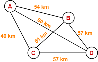
The network consists of 4 hosts distributed as shown below-


Assume this network uses CSMA / CD and signal travels with a speed of 3 x 10⁵ km/sec. If sender sends at 1 Mbps, what could be the minimum size of the packet?

  1. 600 bits
  2. 400 bits
  3. 6000 bits
  4. 1500 bits


Solution-


  • CSMA / CD is a Access Control Method.
  • It is used to provide the access to stations to a broadcast link.
  • In the given network, all the links are point to point.
  • So, there is actually no need of implementing CSMA / CD.
  • Stations can transmit whenever they want to transmit.


In CSMA / CD,

The condition to detect collision is-

Packet size >= 2 x (distance / speed) x Bandwidth


To solve the question,

  • We assume that a packet of same length has to be used in the entire network.
  • To get the minimum length of the packet, what distance we should choose?
  • To get the minimum length of the packet, we should choose the minimum distance.
  • But, then collision would be detected only in the links having distance less than or equal to that minimum distance.
  • For the links, having distance greater than the minimum distance, collision would not be detected.
  • So, we choose the maximum distance so that collision can be detected in all the links of the network.


So, we use the values-

  • Distance = 90 km
  • Speed = 3 x 10⁵ km/sec
  • Bandwidth = 1 Mbps


Substituting these values, we get-

Minimum size of data packet

= 2 x (90 km / 3 x 10⁵ km per sec) x 1 Mbps

= 2 x 30 x 10-5 sec x 106 bits per sec

= 600 bits


Thus, Option (A) is correct.


Next Article- Token Passing | Access Control Method


Get more notes and other study material of Computer Networks.

Watch video lectures by visiting our YouTube channel LearnVidFun.
Ethernet in Networking | Practice Problems

Ethernet in Networking-


Before you go through this article, make sure that you have gone through the previous article on Ethernet.


We have discussed-

  • Ethernet is one of the standard LAN technologies used to build wired LANs.
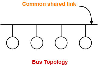
  • Ethernet uses bus topology in which all the stations are connected to a half duplex link.
  • Ethernet uses CSMA / CD as an access control method.


In this article, we will discuss practice problems based on Ethernet.


PRACTICE PROBLEMS BASED ON ETHERNET-


Problem-01:


Which of the following characteristic is most basic to LAN?

  1. Bit rate
  2. Delay x Bandwidth Product
  3. Geographical distance
  4. Cost


Solution-


  • Geographical distance is the basic criteria on which networks are classified.
  • On the basis of geographical distance, networks are classified as LAN, MAN, WAN.
  • Thus,Option (C) is correct.


Problem-02:


On an Ethernet LAN when a collision is detected, the sending station-

  1. continues to send the transmission
  2. temporarily quits the transmission
  3. notifies the destination of an error
  4. permanently quits the transmission


Solution-


  • Ethernet uses CSMA / CD as access control method.
  • On detecting a collision, the sending station temporarily quits the transmission.
  • Transmitting station waits for Back Off time and then tries again.
  • Thus, Option (B) is correct.


Problem-03:


Ethernet implements _________ service for its operation.

  1. connection oriented
  2. connection less
  3. Both A and B
  4. Either A or B


Solution-


REMEMBER

  • Connection oriented service involves allocation of the dedicated resources.
  • Connection less service does not involve allocation of dedicated resources.
  • TCP and Virtual Circuits are connection oriented services.
  • IP, Ethernet and Token Ring are connection less services.
  • Datagrams are connection less, that is why IP is connection less.


When an Ethernet frame is sent,

  • Destination is never expected to reserve the buffer or any other resource for the incoming frame.
  • The data is simply dumped at the destination side.
  • So, it is connectionless.
  • Thus, Option (B) is correct.


Problem-04:


The collision domain of Fast Ethernet is limited to ______ meters.

  1. 2.5
  2. 25
  3. 250
  4. 2500


Solution-


  • Collision domain defines the number of stations that can get involved in the collision when connected to a LAN.
  • In the given question, collision domain refers to maximum distance a LAN can run to detect the collisions.
  • Ethernet uses CSMA / CD as access control method.


In CSMA / CD, condition to detect collisions is-

Distance <= (Length x speed) / (2 x bandwidth)


On substituting the values, we get the value of distance.


REMEMBER

  • For normal Ethernet, collision domain = 2500 meters.
  • For Fast Ethernet, collision domain = 250 meters.
  • For Gigabit Ethernet, collision domain = 25 meters.


Thus, Option (C) is correct.


Problem-05:


The efficiency of Ethernet-

  1. increases when propagation delay and transmission delay are low
  2. increases when propagation delay and transmission delay are high
  3. increases when propagation delay is low and transmission delay is high
  4. increases when propagation delay is high and transmission delay is low


Solution-


  • Efficiency of Ethernet = 1 / ( 1 + 6.44a) where a = Tp / Tt.
  • Thus, Option (C) is correct.


Problem-06:


What is the baud rate of the standard 10 Mbps 802.3 LAN?

  1. 20 mega baud
  2. 10 mega baud
  3. 25 mega baud
  4. 40 mega baud


Solution-


LAN uses Manchester Encoding Technique where-

Baud rate = 2 x Bit rate


For 10 Mbps,

Baud rate

= 2 x 10 mega baud

= 20 mega baud

Thus, Option (A) is correct.


Problem-07:


Consider a 10 Mbps Ethernet LAN that has stations attached to a 2.5 km long coaxial cable. Given that the transmission speed is 2.3 x 10⁸ m/sec, the packet size is 128 bytes out of which 30 bytes are overhead, find the effective transmission rate and maximum rate at which the network can send data.


Solution-


Given-

  • Bandwidth = 10 Mbps
  • Distance = 2.5 km
  • Transmission speed = 2.3 x 10⁸ m/sec
  • Total packet size = 128 bytes
  • Overhead = 30 bytes


Calculating Transmission Delay-


Transmission delay (Tt)

= Packet size / Bandwidth

= 128 bytes / 10 Mbps

= (128 x 8 bits) / (10 x 106 bits per sec)

= 1024 / 107 sec

= 102.4 μsec


Calculating Propagation Delay-


Propagation delay (Tp)

= Distance / Speed

= 2.5 km / (2.3 x 10⁸ m/sec)

= (2.5 x 10³ m) / (2.3 x 10⁸ m/sec)

= 1.08 x 10⁻⁵ sec

= 10.8 μsec


Calculating Value of ‘a’-


a

= Tp / Tt

= 10.8 μsec / 102.4 μsec

= 0.105


Calculating Efficiency-


Efficiency(η)

= 1 / (1 + 6.44 x a)

= 1 / (1 + 6.44 x 0.105)

= 1 / 1.67

= 0.59

= 59%


Calculating Maximum Rate-


Maximum rate or Throughput

= Efficiency x Bandwidth

= 0.59 x 10 Mbps

= 5.9 Mbps


Calculating Effective Transmission Rate-


Effective transmission rate

= Throughput x (128-30 / 128)

= 5.9 Mbps x (98 / 128)

= 0.77 x 5.9 Mbps

= 4.52 Mbps


Problem-08:


The following frame transition diagram shows an exchange of Ethernet frames between two computers, A and B connected via a 10BT Hub. Each frame sent by computer A contains 1500 B of Ethernet payload data, while each frame sent by computer B contains 40 B of Ethernet payload data. Calculate the average utilization of the media during this exchange.


  1. 10%
  2. 1.7%
  3. 20%
  4. 15.2%


Solution-


Calculating Data Sent By Computer A in One Frame-


Given-

  • Each frame sent by computer A contains 1500 B of Ethernet payload data.
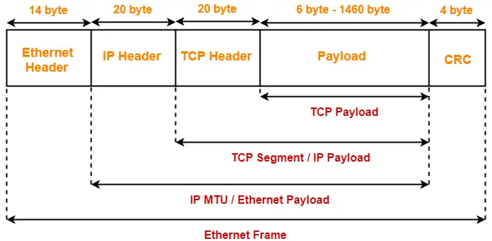
  • This is divided as: 20 bytes of IP Header + 20 bytes of TCP Header + 1460 bytes of data.


So, Total bytes sent by computer A in one frame

= Preamble + SFD + Ethernet Header + Ethernet Payload + CRC

= 7 bytes + 1 byte + 14 bytes + 1500 bytes + 4 bytes

= 1526 bytes


Calculating Data Sent By Computer A in 0.6 Seconds:


Computer A sends 8 frames in 0.6 seconds.

So, Total bytes sent by computer A in 0.6 seconds

= 8 x 1526 bytes

= 12208 bytes


Calculating Data Sent By Computer B in One Frame-


Given-

  • Each frame sent by computer B contains 40 B of Ethernet payload data.
  • This is divided as: 20 bytes of IP Header + 20 bytes of TCP Header + 0 bytes of data.
  • Since minimum data in the payload field of Ethernet must 46 bytes. So, extra 6 bytes are padded.


So, Total bytes sent by computer B in one frame

= Preamble + SFD + Ethernet Header + Ethernet Payload + CRC

= 7 bytes + 1 byte + 14 bytes + (40 bytes + 6 bytes) + 4 bytes

= 72 bytes


Calculating Data Sent By Computer B in 0.6 Seconds-


Computer B sends 4 frames in 0.6 seconds.

So, Total bytes sent by computer B in 0.6 seconds

= 4 x 72 bytes

= 288 bytes


Calculating Total Data Sent in 0.6 Seconds:


Total data flow that takes place in 0.6 seconds

= Total data sent by computer A in 0.6 seconds + Total data sent by computer B in 0.6 seconds

= 12208 bytes + 288 bytes

= 12496 bytes

= 99968 bits


Calculating Throughput-


Throughput

= Amount of data that flows per second

= 99968 bits / 0.6 seconds

= 166613.33 bits/sec


Calculating Utilization-


Throughput = Efficiency x Bandwidth

So, Efficiency or Utilization

= Throughput / Bandwidth

= (166613.33 bits per sec) / 10 Mbps

= 0.017

= 1.7%


Thus, Option (B) is correct.


Problem-09:


Ethernet adaptor receives all frames and accepts-

  1. Frames addressed to its own address
  2. Frames addressed to the multicast or broadcast address
  3. Frames if it has been placed in promiscuous mode
  4. All of the above


Solution-


In a bus topology Ethernet,

  • Ethernet Adaptor enables a computer to access an Ethernet Network.
  • If one station sends a frame to other station, then other stations & Ethernet Adaptor also receives that frame.
  • But they accept only those frames which are destined for them.
  • Ethernet Adaptor accepts all those frames which are addressed to its own address or broadcast address or multicast address (if it is present in that multicast group)
  • Network administrator may set the network in promiscuous mode.
  • This is done to monitor the activities going on in the network.
  • So, if Ethernet Adaptor is set in promiscuous mode, it receives and accepts all the frames.
  • Thus, Option (D) is correct.


Next Article- Types of Switching | Circuit Switching


Get more notes and other study material of Computer Networks.

Watch video lectures by visiting our YouTube channel LearnVidFun.

Ethernet in Networking | Ethernet Frame Format

Local Area Network-


  • A Local Area Network (LAN) is a network of computers.
  • It is confined to a small area which may be a room, building or a group of buildings.
  • A LAN may be wired, wireless or a combination of the two.


LAN Technologies-


Standard technologies used to build a wired LAN are-


  1. Ethernet
  2. Token Ring


In this article, we will discuss about Ethernet and its Frame Format.


Ethernet-


  • Ethernet is one of the standard LAN technologies used for building wired LANs.
  • It is defined under IEEE 802.3.


Characteristics-


Point-01:


  • Ethernet uses bus topology.
  • In bus topology, all the stations are connected to a single half duplex link.


Point-02:


  • Ethernet uses CSMA / CD as access control method to deal with the collisions.


Point-03:


  • Ethernet uses Manchester Encoding Technique for converting data bits into signals.


Point-04:


  • For Normal Ethernet, operational bandwidth is 10 Mbps.
  • For Fast Ethernet, operational bandwidth is 100 Mbps.
  • For Gigabit Ethernet, operational bandwidth is 1 Gbps.


Ethernet Frame Format-


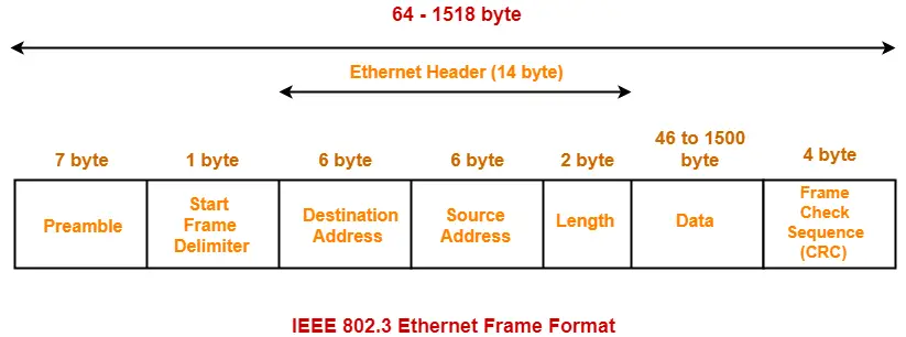
IEEE 802.3 defines the following Ethernet frame format-


1. Preamble-


  • It is a 7 byte field that contains a pattern of alternating 0’s and 1’s.
  • It alerts the stations that a frame is going to start.
  • It also enables the sender and receiver to establish bit synchronization.


2. Start Frame Delimiter (SFD)-


  • It is a 1 byte field which is always set to 10101011.
  • The last two bits “11” indicate the end of Start Frame Delimiter and marks the beginning of the frame.


NOTES

  • The above two fields are added by the physical layer and represents the physical layer header.
  • Sometimes, Start Frame Delimiter (SFD) is considered to be a part of Preamble.
  • That is why, at many places, Preamble field length is described as 8 bytes.


3. Destination Address-


  • It is a 6 byte field that contains the MAC address of the destination for which the data is destined.


4. Source Address-


  • It is a 6 byte field that contains the MAC address of the source which is sending the data.


5. Length-


  • It is a 2 byte field which specifies the length (number of bytes) of the data field.
  • This field is required because Ethernet uses variable sized frames.


NOTES

  • The maximum value that can be accommodated in this field = 216 – 1 = 65535.
  • But it does not mean maximum data that can be sent in one frame is 65535 bytes.
  • The maximum amount of data that can be sent in a Ethernet frame is 1500 bytes.
  • This is to avoid the monopoly of any single station.


The following three fields collectively represents the Ethernet Header

  • Destination Address (6 bytes)
  • Source Address (6 bytes)
  • Length (2 bytes)

Thus, Ethernet Header Size = 14 bytes.


6. Data-


  • It is a variable length field which contains the actual data.
  • It is also called as a payload field.
  • The length of this field lies in the range [ 46 bytes , 1500 bytes ].
  • Thus, in a Ethernet frame, minimum data has to be 46 bytes and maximum data can be 1500 bytes.


Minimum Length of Data Field


  • Ethernet uses CSMA / CD as access control method to deal with collisions.
  • For detecting the collisions, CSMA / CD requires-

Minimum length of data packet = 2 x Propagation delay x Bandwidth

  • Substituting the standard values of Ethernet, it is found that minimum length of the Ethernet frame has to be 64 bytes starting from the destination address field to the CRC field and 72 bytes including the Preamble and SFD fields.
  • Therefore, minimum length of the data field has to be = 64 bytes – (6+6+2+4) bytes = 46 bytes


Maximum Length of Data Field


  • The maximum amount of data that can be sent in a Ethernet frame is 1500 bytes.
  • This is to avoid the monopoly of any single station.
  • If Ethernet allows the frames of big sizes, then other stations may not get the fair chance to send their data.


7. Frame Check Sequence (CRC)-


  • It is a 4 byte field that contains the CRC code for error detection.


Advantages of Using Ethernet-


  • It is simple to understand and implement.
  • Its maintenance is easy.
  • It is cheap.


Limitations of Using Ethernet-


Point-01:


  • It can not be used for real time applications.
  • Real time applications require the delivery of data within some time limit.
  • Ethernet is not reliable because of high probability of collisions.
  • High number of collisions may cause a delay in delivering the data to its destination.


Point-02:


  • It can not be used for interactive applications.
  • Interactive applications like chatting requires the delivery of even very small amount of data.
  • Ethernet requires that minimum length of the data must be 46 bytes.


Point-03:


  • It can not be used for client server applications.
  • Client server applications require that server must be given higher priority than clients.
  • Ethernet has no facility to set priorities.


Token Ring overcomes these limitations of Ethernet.


Important Concept-


For data transmission-

  • TCP segment sits inside the IP datagram payload field.
  • IP datagram sits inside the Ethernet payload field.


Next Article- Practice Problems On Ethernet


Get more notes and other study material of Computer Networks.

Watch video lectures by visiting our YouTube channel LearnVidFun.

Flow Control Protocols | Practice Problems

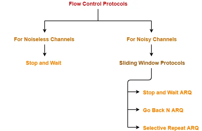
Flow Control Protocols-


In computer networking, there are various flow control protocols-


In this article, we will discuss practice problems based on these flow control protocols.


PRACTICE PROBLEMS BASED ON FLOW CONTROL PROTOCOLS-


Problem-01:


In what protocols is it possible for the sender to receive an acknowledgement for a packet that falls outside its current window?

  1. Stop and Wait
  2. Selective Repeat
  3. Go back N
  4. All of the above


Solution-


  • Delayed Acknowledgements fall outside the current window.
  • They may occur in any of the flow control protocols and received by the sender.


Thus, correct option is (D).


Problem-02:


On a wireless link, the probability of packet error is 0.2. A stop and wait protocol is used to transfer data across the link. The channel condition is assumed to be independent from transmission to transmission. What is the average number of transmission attempts required to transfer 100 packets?

  1. 100
  2. 125
  3. 150
  4. 200


Solution-


Method-01:


Given-

  • Probability of packet error = 0.2
  • We have to transfer 100 packets


Now,

  • When we transfer 100 packets, number of packets in which error will occur = 0.2 x 100 = 20.
  • Then, these 20 packets will have to be retransmitted.
  • When we retransmit 20 packets, number of packets in which error will occur = 0.2 x 20 = 4.
  • Then, these 4 packets will have to be retransmitted.
  • When we retransmit 4 packets, number of packets in which error will occur = 0.2 x 4 = 0.8 ≅ 1.
  • Then, this 1 packet will have to be retransmitted.


From here, average number of transmission attempts required = 100 + 20 + 4 + 1 = 125.

Thus, Option (B) is correct.


Method-02:


REMEMBER

If there are n packets to be transmitted and p is the probability of packet error, then-

Number of transmission attempts required

= n + np + np2 + np3 + …… + ∞

= n / (1-p)


Substituting the given values, we get-

Average number of transmission attempts required = 100 / (1-0.2) = 125.

Thus, Option (B) is correct.


Problem-03:


Compute the fraction of the bandwidth that is wasted on overhead (headers and retransmissions) for a protocol on a heavily loaded 50 Kbps satellite channel with data frames consisting of 40 bits header and 3960 data bits. Assume that the signal propagation time from the earth to the satellite is 270 msec. ACK frames never occur. NAK frames are 40 bits. The error rate for data frames is 1% and the error rate for NAK frames is negligible.

  1. 1.21 %
  2. 2.12 %
  3. 1.99 %
  4. 1.71 %


Solution-


Consider 100 frames are being sent. Then, we have-


Useful Data Sent-


Since each frame contains 3960 data bits, so while sending 100 frames,

Useful data sent

= 100 x 3960 bits

= 396000 bits


Useless Data Sent / Overhead-


In general, overhead is due to headers, retransmissions and negative acknowledgements.


Now,

  • The error rate for data frames is 1%, therefore out of 100 sent frames, error occurs in one frame.
  • This causes the negative acknowledgement to follow which causes the retransmission.


So, we have-

  • Overhead due to headers = 100 x 40 bits = 400 bits.
  • Overhead due to negative acknowledgement = 40 bits.
  • Overhead due to retransmission = 40 bits header + 3960 data bits = 4000 bits.


From here,

Total overhead

= 400 bits + 40 bits + 4000 bits

= 8040 bits


Calculating Efficiency-


Efficiency (η) = Useful data sent / Total data sent


Here,

  • Useful data sent = 396000 bits
  • Total data sent = Useful data sent + Overhead = 396000 bits + 8040 bits = 404040 bits


Substituting the values, we get-

Efficiency (η)

= 396000 bits / 404040 bits

= 0.9801


Calculating Bandwidth Utilization-


Bandwidth Utilization

= Efficiency x Bandwidth

= 0.9801 x 50 Kbps

= 49.005 Kbps


Calculating Bandwidth Wasted-


Bandwidth wasted

= Bandwidth – Bandwidth Utilization

= 50 Kbps – 49.005 Kbps

= 0.995 Kbps


Calculating Fraction of Bandwidth Wasted-


Fraction of bandwidth wasted

= Wasted Bandwidth / Total Available Bandwidth

= 0.995 Kbps / 50 Kbps

= 0.0199

= 1.99 %


Thus, Option (C) is correct.


Problem-04:


Consider 1 Mbps error free line. The maximum frame size is 1000 bits. New packets are generated about 1 sec apart. The time out interval is 10 msec. If the ack timer is eliminated. How many times the average message be transmitted?


  1. Only once
  2. Twice
  3. Thrice
  4. Can’t say


Solution-


  • Transmission delay (Tt) = L / B = 1000 bits / 106 bits per sec = 1 msec.
  • After packet is put on the link, the time out timer is started which is 10 msec long.
  • The next packet is transmitted after 1 sec = 1000 msec.
  • If no acknowledgement is received within 10 msec, the packet will be retransmitted.
  • We have been asked how many times the average message be transmitted i.e. how many retransmissions are possible.
  • Retransmission occurs or not depends on the propagation delay (Tp).
  • If Tp is more, time out will occur and retransmission will take place but if Tp is less, then there will be no time out.
  • Since propagation delay (Tp) is not given in the question, therefore we can not say anything.


Thus, Option (D) is correct.


Problem-05:


What is the effect on line utilization if we increase the number of frames for a constant message size?


  1. Lower line efficiency
  2. Higher line efficiency
  3. No change in line efficiency
  4. No relation between line efficiency and frame size


Solution-


In both the following cases, line utilization remains the same-

  • Whether the entire message is sent as a single entity
  • Or the entire message is divided into frames and then frames are sent.

This is because line contains the same amount of data in both cases.


So,

  • If the number of frames are increased by dividing the message, there is no change in line efficiency.
  • The line efficiency remains the same.


Thus, Option (C) is correct.


Next Article- Flow Control Methods | Single Parity Check


Get more notes and other study material of Computer Networks.

Watch video lectures by visiting our YouTube channel LearnVidFun.