Tag: Computer Networks Basics

Error Detection in Computer Networks | Parity Check

Error Detection in Computer Networks-


When sender transmits data to the receiver, the data might get scrambled by noise or data might get corrupted during the transmission.


Error detection is a technique that is used to check if any error occurred in the data during the transmission.


Error Detection Methods-


Some popular error detection methods are-


  1. Single Parity Check
  2. Cyclic Redundancy Check (CRC)
  3. Checksum


In this article, we will discuss about Single Parity Check.


Single Parity Check-


In this technique,

  • One extra bit called as parity bit is sent along with the original data bits.
  • Parity bit helps to check if any error occurred in the data during the transmission.


Steps Involved-


Error detection using single parity check involves the following steps-


Step-01:


At sender side,

  • Total number of 1’s in the data unit to be transmitted is counted.
  • The total number of 1’s in the data unit is made even in case of even parity.
  • The total number of 1’s in the data unit is made odd in case of odd parity.
  • This is done by adding an extra bit called as parity bit.


Step-02:


  • The newly formed code word (Original data + parity bit) is transmitted to the receiver.


Step-03:


At receiver side,

  • Receiver receives the transmitted code word.
  • The total number of 1’s in the received code word is counted.


Then, following cases are possible-

  • If total number of 1’s is even and even parity is used, then receiver assumes that no error occurred.
  • If total number of 1’s is even and odd parity is used, then receiver assumes that error occurred.
  • If total number of 1’s is odd and odd parity is used, then receiver assumes that no error occurred.
  • If total number of 1’s is odd and even parity is used, then receiver assumes that error occurred.


Parity Check Example-


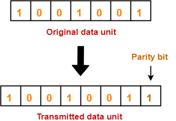
Consider the data unit to be transmitted is 1001001 and even parity is used.

Then,


At Sender Side-


  • Total number of 1’s in the data unit is counted.
  • Total number of 1’s in the data unit = 3.
  • Clearly, even parity is used and total number of 1’s is odd.
  • So, parity bit = 1 is added to the data unit to make total number of 1’s even.
  • Then, the code word 10010011 is transmitted to the receiver.


At Receiver Side-


  • After receiving the code word, total number of 1’s in the code word is counted.
  • Consider receiver receives the correct code word = 10010011.
  • Even parity is used and total number of 1’s is even.
  • So, receiver assumes that no error occurred in the data during the transmission.


Advantage-


  • This technique is guaranteed to detect an odd number of bit errors (one, three, five and so on).
  • If odd number of bits flip during transmission, then receiver can detect by counting the number of 1’s.


Also Read- Checksum


Limitation-


  • This technique can not detect an even number of bit errors (two, four, six and so on).
  • If even number of bits flip during transmission, then receiver can not catch the error.


EXAMPLE


  • Consider the data unit to be transmitted is 10010001 and even parity is used.
  • Then, code word transmitted to the receiver = 100100011
  • Consider during transmission, code word modifies as 101100111. (2 bits flip)
  • On receiving the modified code word, receiver finds the number of 1’s is even and even parity is used.
  • So, receiver assumes that no error occurred in the data during transmission though the data is corrupted.


To gain better understanding about single parity check,

Watch this Video Lecture


Next Article- Cyclic Redundancy Check


Get more notes and other study material of Computer Networks.

Watch video lectures by visiting our YouTube channel LearnVidFun.
Cyclic Redundancy Check | CRC | Example

Error Detection in Computer Networks-


Error detection is a technique that is used to check if any error occurred in the data during the transmission.


Some popular error detection methods are-


  1. Single Parity Check
  2. Cyclic Redundancy Check (CRC)
  3. Checksum


In this article, we will discuss about Cyclic Redundancy Check (CRC).


Cyclic Redundancy Check-


  • Cyclic Redundancy Check (CRC) is an error detection method.
  • It is based on binary division.


CRC Generator-


  • CRC generator is an algebraic polynomial represented as a bit pattern.
  • Bit pattern is obtained from the CRC generator using the following rule-


The power of each term gives the position of the bit and the coefficient gives the value of the bit.


Example-


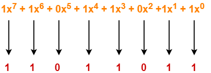
Consider the CRC generator is x7 + x6 + x4 + x3 + x + 1.

The corresponding binary pattern is obtained as-


Thus, for the given CRC generator, the corresponding binary pattern is 11011011.


Properties Of CRC Generator-


The algebraic polynomial chosen as a CRC generator should have at least the following properties-


Rule-01:


  • It should not be divisible by x.
  • This condition guarantees that all the burst errors of length equal to the length of polynomial are detected.


Rule-02:


  • It should be divisible by x+1.
  • This condition guarantees that all the burst errors affecting an odd number of bits are detected.


Important Notes-


If the CRC generator is chosen according to the above rules, then-

  • CRC can detect all single-bit errors
  • CRC can detect all double-bit errors provided the divisor contains at least three logic 1’s.
  • CRC can detect any odd number of errors provided the divisor is a factor of x+1.
  • CRC can detect all burst error of length less than the degree of the polynomial.
  • CRC can detect most of the larger burst errors with a high probability.


Steps Involved-


Error detection using CRC technique involves the following steps-


Step-01: Calculation Of CRC At Sender Side-


At sender side,

  • A string of n 0’s is appended to the data unit to be transmitted.
  • Here, n is one less than the number of bits in CRC generator.
  • Binary division is performed of the resultant string with the CRC generator.
  • After division, the remainder so obtained is called as CRC.
  • It may be noted that CRC also consists of n bits.


Step-02: Appending CRC To Data Unit-


At sender side,

  • The CRC is obtained after the binary division.
  • The string of n 0’s appended to the data unit earlier is replaced by the CRC remainder.


Step-03: Transmission To Receiver-


  • The newly formed code word (Original data + CRC) is transmitted to the receiver.


Step-04: Checking at Receiver Side-


At receiver side,

  • The transmitted code word is received.
  • The received code word is divided with the same CRC generator.
  • On division, the remainder so obtained is checked.


The following two cases are possible-


Case-01: Remainder = 0


If the remainder is zero,

  • Receiver assumes that no error occurred in the data during the transmission.
  • Receiver accepts the data.


Case-02: Remainder ≠ 0


If the remainder is non-zero,

  • Receiver assumes that some error occurred in the data during the transmission.
  • Receiver rejects the data and asks the sender for retransmission.


Also Read- Parity Check


PRACTICE PROBLEMS BASED ON CYCLIC REDUNDANCY CHECK (CRC)-


Problem-01:


A bit stream 1101011011 is transmitted using the standard CRC method. The generator polynomial is x4+x+1. What is the actual bit string transmitted?


Solution-


  • The generator polynomial G(x) = x4 + x + 1 is encoded as 10011.
  • Clearly, the generator polynomial consists of 5 bits.
  • So, a string of 4 zeroes is appended to the bit stream to be transmitted.
  • The resulting bit stream is 11010110110000.


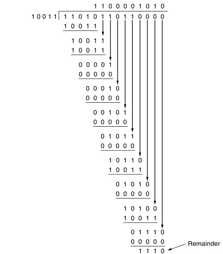
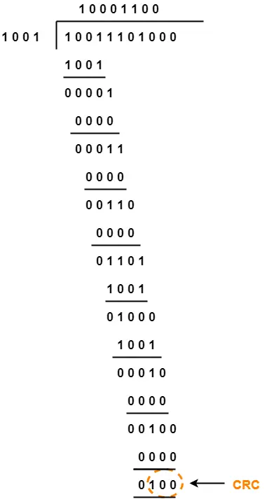
Now, the binary division is performed as-


From here, CRC = 1110.

Now,

  • The code word to be transmitted is obtained by replacing the last 4 zeroes of 11010110110000 with the CRC.
  • Thus, the code word transmitted to the receiver = 11010110111110.


Problem-02:


A bit stream 10011101 is transmitted using the standard CRC method. The generator polynomial is x3+1.

  1. What is the actual bit string transmitted?
  2. Suppose the third bit from the left is inverted during transmission. How will receiver detect this error?


Solution-


Part-01:


  • The generator polynomial G(x) = x3 + 1 is encoded as 1001.
  • Clearly, the generator polynomial consists of 4 bits.
  • So, a string of 3 zeroes is appended to the bit stream to be transmitted.
  • The resulting bit stream is 10011101000.


Now, the binary division is performed as-


From here, CRC = 100.

Now,

  • The code word to be transmitted is obtained by replacing the last 3 zeroes of 10011101000 with the CRC.
  • Thus, the code word transmitted to the receiver = 10011101100.


Part-02:


According to the question,

  • Third bit from the left gets inverted during transmission.
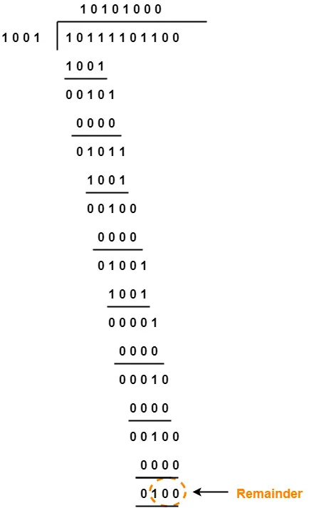
  • So, the bit stream received by the receiver = 10111101100.


Now,

  • Receiver receives the bit stream = 10111101100.
  • Receiver performs the binary division with the same generator polynomial as-


From here,

  • The remainder obtained on division is a non-zero value.
  • This indicates to the receiver that an error occurred in the data during the transmission.
  • Therefore, receiver rejects the data and asks the sender for retransmission.


To watch video solution, click here.


To gain better understanding about Cyclic Redundancy Check,

Watch this Video Lecture


Next Article- Checksum


Get more notes and other study material of Computer Networks.

Watch video lectures by visiting our YouTube channel LearnVidFun.
Stop and Wait ARQ | Go back N | SR Protocol

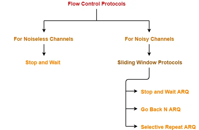
Flow Control Protocols-


In computer networking, there are various flow control protocols-


Sliding Window Protocol-


  • Sliding window protocol allows the sender to send multiple frames before needing the acknowledgements.
  • It is more efficient.


Read More- Sliding Window Protocol


Implementations-


Various implementations of sliding window protocol are-

  1. Stop and Wait ARQ
  2. Go back N
  3. Selective Repeat


In this article, we will compare these sliding window protocols.


Comparison Table-


Stop and Wait ARQ Go back N Selective Repeat Remarks
Efficiency 1 / (1+2a) N / (1+2a) N / (1+2a) Go back N and Selective Repeat gives better efficiency than Stop and Wait ARQ.
Window Size Sender Window Size = 1

Receiver Window Size = 1

Sender Window Size = N

Receiver Window Size = 1

Sender Window Size = N

Receiver Window Size = N

Buffer requirement in Selective Repeat is very large.

If the system does not have lots of memory, then it is better to choose Go back N.

Minimum number of sequence numbers required 2 N+1 2 x N Selective Repeat requires large number of bits in sequence number field.
Retransmissions required if a packet is lost Only the lost packet is retransmitted The entire window is retransmitted Only the lost packet is retransmitted Selective Repeat is far better than Go back N in terms of retransmissions required.
Bandwidth Requirement Bandwidth requirement is Low Bandwidth requirement is high because even if a single packet is lost, entire window has to be retransmitted.

Thus, if error rate is high, it wastes a lot of bandwidth.

Bandwidth requirement is moderate Selective Repeat is better than Go back N in terms of bandwidth requirement.
CPU usage Low Moderate High due to searching and sorting required at sender and receiver side Go back N is better than Selective Repeat in terms of CPU usage.
Level of difficulty in Implementation Low Moderate Complex as it requires extra logic and sorting and searching Go back N is better than Selective Repeat in terms of implementation difficulty.
Acknowledgements Uses independent acknowledgement for each packet Uses cumulative acknowledgements (but may use independent acknowledgements as well) Uses independent acknowledgement for each packet Sending cumulative acknowledgements reduces the traffic in the network but if it is lost, then the ACKs for all the corresponding packets are lost.
Type of Transmission Half duplex Full duplex Full duplex Go back N and Selective Repeat are better in terms of channel usage.


Conclusions-


  • Go back N is more often used than other protocols.
  • SR protocol is less used because of its complexity.
  • Stop and Wait ARQ is less used because of its low efficiency.
  • Depending on the context and resources availability, Go back N or Selective Repeat is employed.
  • Selective Repeat and Stop and Wait ARQ are similar in terms of retransmissions.
  • Go back N and Selective Repeat are similar in terms of efficiency if sender window sizes are same.
  • SR protocol may be considered as a combination of advantages of Stop and Wait ARQ and Go back N.
  • SR protocol is superior to other protocols but because of its complexity, it is less used.


Important Notes-


Note-01:


Protocols at data link layer like HDLC (Low level protocols) use Go back N.

This is because-

  1. Bandwidth is high
  2. CPU is very busy doing routing job
  3. Error rate is low since out of order packets are not possible in wired medium


Note-02:


Protocols at transport layer like TCP (High level protocols) use selective repeat.


PRACTICE PROBLEMS BASED ON SLIDING WINDOW PROTOCOLS-


Problem-01:


If the bandwidth between the sender and receiver is sufficient, CPU and buffers are moderate, then which flow control protocol would you suggest to use?


Solution-


The suggested protocol would be Go back N.


Problem-02:


If the bandwidth between the sender and receiver is moderate, CPU and buffers are sufficient, then which flow control protocol would you suggest to use?


Solution-


The suggested protocol would be Selective Repeat.


To gain better understanding about sliding window protocols comparison,

Watch this Video Lecture


Next Article- Miscellaneous Problems On Flow Control Protocols


Get more notes and other study material of Computer Networks.

Watch video lectures by visiting our YouTube channel LearnVidFun.
Transmission Control Protocol | Practice Problems

PRACTICE PROBLEMS BASED ON TRANSMISSION CONTROL PROTOCOL-


Problem-01:


How many TCP connections can be opened between two ports?

  1. Multiple
  2. Single
  3. Zero
  4. None


Solution-


Option (B) is correct.


Problem-02:


TCP protects itself from miss delivery by IP with the help of-

  1. Source IP Address in IP header
  2. Destination IP Address in IP header
  3. Pseudo header
  4. Source port and Destination port


Solution-


Option (C) is correct.


Problem-03:


What addressing system has topological significance?

  1. Logical or Network Address
  2. LAN or Physical Address
  3. Port Addressing System
  4. Multicast Addressing System


Solution-


Option (A) is correct.


Problem-04:


If WAN link is 2 Mbps and RTT between source and destination is 300 msec, what would be the optimal TCP window size needed to fully utilize the line?

  1. 60,000 bits
  2. 75,000 bytes
  3. 75,000 bits
  4. 60,000 bytes


Solution-


Given-

  • Bandwidth = 2 Mbps
  • RTT = 300 msec


Optimal TCP Window Size-


Optimal TCP window size

= Maximum amount of data that can be sent in 1 RTT

= 2 Mbps x 300 msec

= 600 x 103 bits

= 60,0000 bits

= 75,000 bytes


Thus, Option (B) is correct.


Problem-05:


Suppose host A is sending a large file to host B over a TCP connection. The two end hosts are 10 msec apart (20 msec RTT) connected by a 1 Gbps link. Assume that they are using a packet size of 1000 bytes to transmit the file. For simplicity, ignore ack packets. At least how big would the window size (in packets) have to be for the channel utilization to be greater than 80%?

  1. 1000
  2. 1500
  3. 2000
  4. 2500


Solution-


Given-

  • RTT = 20 msec
  • Bandwidth = 1 Gbps
  • Packet size = 1000 bytes
  • Efficiency >= 80%


Window Size For 100% Efficiency-


For 100% efficiency,

Window size

= Maximum number of bits that can be transmitted in 1 RTT

= 1 Gbps x 20 msec

= (109 bits per sec) x 20 x 10-3 sec

= 20 x 106 bits

= 2 x 107 bits


Window Size For 80% Efficiency-


For 80% efficiency,

Window size

= 0.8 x 2 x 107 bits

= 1.6 x 107 bits


In terms of packets,

Window size

= 1.6 x 107 bits / Packet size

= 1.6 x 107 bits / (1000 x 8 bits)

= 0.2 x 10⁴ packets

= 2000 packets


Thus, Option (C) is correct.


Problem-06:


A TCP machine is sending windows of 65535 B over a 1 Gbps channel that has a 10 msec one way delay.

  1. What is the maximum throughput achievable?
  2. What is the line efficiency?


Solution-


Given-

  • Window size = 65535 bytes
  • Bandwidth = 1 Gbps
  • One way delay = 10 msec


Method-01:


Maximum amount of data that can be sent in 1 RTT

= 1 Gbps x (2 x 10 msec)

= (109 bits per sec) x 20 x 10-3 sec

= 20 x 106 bits

= 25 x 105 bytes


Amount of data that is actually being sent in 1 RTT = 65535 bytes


Thus,

Line Efficiency(η)

= Amount of data being sent in 1 RTT / Maximum amount of data that can be sent in 1 RTT

= 65535 bytes / 25 x 105 bytes

= 0.026214

= 2.62%


Now,

Maximum Achievable Throughput

= Efficiency x Bandwidth

= 0.0262 x 1 Gbps

= 26.214 Mbps


Method-02:


Maximum Achievable Throughput

= Number of bits sent per second

= 65535 B / 20 msec

= (65535 x 8 bits) / (20 x 10-3 sec)

= 26.214 Mbps


Now,

Line Efficiency

= Throughput / Bandwidth

= 26.214 Mbps / 1 Gbps

= 26.214 x 10-3

= 0.026214

= 2.62%


Next Article- TCP Congestion Control


Get more notes and other study material of Computer Networks.

Watch video lectures by visiting our YouTube channel LearnVidFun.
IP Header | IP Fragmentation | Problems

IP Fragmentation-


Before you go through this article, make sure that you have gone through the previous article on IP Fragmentation.


We have discussed-

  • IP Fragmentation is a process of dividing the datagram into fragments during its transmission.
  • It is performed by intermediary devices at destination side at network layer.


Also Read- IP Header


In this article, we will discuss practice problems based on IP Header and IP Fragmentation.


PRACTICE PROBLEMS BASED ON IP HEADER AND IP FRAGMENTATION-


Problem-01:


The intermediate routers between source and destination need the following information in IP header-

  1. Version
  2. Protocol
  3. Identification Number
  4. Source IP Address


Solution-


Option-A:


  • Version field indicates the version of IP used.
  • This information is required to process the packet appropriately based on its version.


Option-B:


  • Protocol field indicates the next level protocol.
  • This information is required by the router to accept or discard the packet if its buffer is full.
  • Based on the priority, router takes its decision.


Option-C:


  • Identification number field identifies the fragments of the same datagram.
  • This information is required while re-assembling the datagram fragments.


Option-D:


  • Source IP Address field indicates the IP Address of the source.
  • This information is required by the router to send ICMP packet to the source.
  • ICMP packet informs the source that its packet has been discarded.


Thus, All these fields are required in the IP Header.


Problem-02:


Fragmentation of a datagram is needed in-

  1. Datagram circuit only
  2. Virtual circuit only
  3. Both (A) and (B)
  4. None


Solution-


  • Each network has its Maximum Transmission Unit (MTU).
  • If the size of data packet is greater than MTU, then it will have divided into fragments to transmit it through the network.
  • So, fragmentation may be required in datagram circuits as well as virtual circuits.
  • Thus, Option (C) is correct.


Problem-03:


What are all the fields required from IP header to allow the destination to perform reassembly of fragments?

  1. Identification, MF, Offset, Header length and Total length
  2. MF, Offset and Destination IP
  3. MF, Datagram length, Source IP
  4. MF, Options and Offset


Solution-


Clearly, Option (A) is correct.


Problem-04:


The checksum in IP must be recomputed at every router because of change in ____ fields.

  1. TTL, Options, Identification Number, Offset
  2. TTL, Options, Datagram Length, Offset
  3. TTL, Options, Data, Offset
  4. TTL, Header Length, Offset, ToS


Solution-


Clearly, Option (B) is correct.


Problem-05:


If the value available in “fragment offset” field of IP header is 100, then the number of bytes ahead of this fragment is ___ ?

  1. 100 B
  2. 400 B
  3. 800 B
  4. 200 B


Solution-


  • Fragment offset field use a scaling factor of 8.
  • If Fragment offset field value = 100, then fragment offset = 8 x 100 = 800.
  • It suggests 800 bytes of data is ahead of this fragment.
  • Thus, Option (C) is correct.


Problem-06:


When the source does not trust the routers to route properly or source wishes to make sure that the packet does not stray from specified path, what options can be used?

  1. Loose source routing
  2. Trace route
  3. Strict source routing
  4. Internet Time Stamp


Solution-


Clearly, Option (C) is correct.


Problem-07:


The checksum computation in IP header includes-

  1. IP header only
  2. IP header and data
  3. IP header and Pseudo header
  4. None


Solution-


  • Checksum computation in IP header includes IP header only.
  • Errors in the data field are handled by the encapsulated protocol.
  • Thus, Option (A) is correct.


Problem-08:


Suppose a router receives an IP packet containing 600 data bytes and has to forward the packet to a network with maximum transmission unit of 200 bytes. Assume that IP header is 20 bytes long. What are fragment offset values for divided packets?

  1. 22, 44, 66, 88
  2. 0, 22, 44
  3. 0, 22, 44, 66
  4. 22, 44, 66


Solution-


Given-

  • MTU size of the destination network = 200 bytes
  • IP header length = 20


Now,

  • Maximum amount of data that can be sent in one fragment = 200 – 20 = 180 bytes.
  • Amount of data sent in a fragment must be a multiple of 8.
  • So, maximum data sent that can be in one fragment = 176 bytes.


Thus, 4 fragments are created-

  • 1st fragment contains 176 bytes of data.
  • 2nd fragment contains 176 bytes of data.
  • 3rd fragment contains 176 bytes of data.
  • 4th fragment contains 72 bytes of data


So,

  • Fragment offset value for 1st fragment = 0
  • Fragment offset value for 2nd fragment = 176 / 8 = 22
  • Fragment offset value for 3rd fragment = (176+176) / 8 = 44
  • Fragment offset value for 4th fragment = (176 + 176 + 176) / 8 = 66


Thus, Option (C) is correct.


To watch video solution and practice other problems,

Watch this Video Lecture


Next Article- Transmission Control Protocol | TCP


Get more notes and other study material of Computer Networks.

Watch video lectures by visiting our YouTube channel LearnVidFun.