Tag: Basics of Computer Networks

Stop and Wait ARQ | Sliding Window Protocols

Stop and Wait Protocol-


Before you go through this article, make sure that you have gone through the previous article on Stop and Wait Protocol.


In stop and wait protocol,

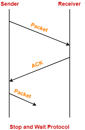
  • Sender sends one data packet and then waits for its acknowledgement.
  • Sender sends the next packet only after it receives the acknowledgement for the previous packet.


The main problem faced by the Stop and Wait protocol is the occurrence of deadlock due to-

  1. Loss of data packet
  2. Loss of acknowledgement


Stop and Wait ARQ-


Stop and Wait ARQ is an improved and modified version of Stop and Wait protocol.


Stop and Wait ARQ assumes-

  • The communication channel is noisy.
  • Errors may get introduced in the data during the transmission.


Working-


  • Stop and wait ARQ works similar to stop and wait protocol.
  • It provides a solution to all the limitations of stop and wait protocol.
  • Stop and wait ARQ includes the following three extra elements.


Thus, we can say-


Stop and Wait ARQ

= Stop and Wait Protocol + Time Out Timer + Sequence Numbers for Data Packets and Acknowledgements


Number of Sequence Numbers Required-


NOTE

For any sliding window protocol to work without any problem,

the following condition must be satisfied-

Available Sequence Numbers >= Sender Window Size + Receiver Window Size


Stop and wait ARQ is a one bit sliding window protocol where-

  • Sender window size = 1
  • Receiver window size = 1


Thus, in stop and wait ARQ,

Minimum number of sequence numbers required

= Sender Window Size + Receiver Window Size

= 1 + 1

= 2


Thus,

  • Minimum number of sequence numbers required in Stop and Wait ARQ = 2.
  • The two sequence numbers used are 0 and 1.


How Stop and Wait ARQ Solves All Problems?


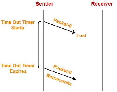
1. Problem of Lost Data Packet-


  • Time out timer helps to solve the problem of lost data packet.
  • After sending a data packet  to the receiver, sender starts the time out timer.
  • If the data packet gets acknowledged before the timer expires, sender stops the time out timer.
  • If the timer goes off before receiving the acknowledgement, sender retransmits the same data packet.
  • After retransmission, sender resets the timer.
  • This prevents the occurrence of deadlock.


2. Problem of Lost Acknowledgement-


  • Sequence number on data packets help to solve the problem of delayed acknowledgement.
  • Consider the acknowledgement sent by the receiver gets lost.
  • Then, sender retransmits the same data packet after its timer goes off.
  • This prevents the occurrence of deadlock.
  • The sequence number on the data packet helps the receiver to identify the duplicate data packet.
  • Receiver discards the duplicate packet and re-sends the same acknowledgement.
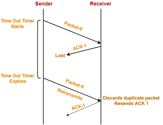


Role of Sequence Number on Data Packets


Consider the above example-


Step-01:


  • Sender sends a data packet with sequence number-0 to the receiver.


Step-02:


  • Receiver receives the data packet correctly.
  • Receiver now expects data packet with sequence number-1.
  • Receiver sends the acknowledgement ACK-1.


Step-03:


  • Acknowledgement ACK-1 sent by the receiver gets lost on the way.


Step-04:


  • Sender receives no acknowledgement and time out occurs.
  • Sender retransmits the same data packet with sequence number-0.
  • This will be a duplicate packet for the receiver.


Step-05:


  • Receiver receives the data packet and discovers it is the duplicate packet.
  • It expects the data packet with sequence number-1 but receiving the data packet with sequence number-0.
  • It discards the duplicate data packet and re-sends acknowledgement ACK-1.
  • ACK-1 requests the sender to send a data packet with sequence number-1.
  • This avoids the inconsistency of data.


Conclusion-


  • Had the sequence numbers not been allotted to the data packets, receiver would have accepted the duplicate data packet thinking of it as the new data packet.
  • This is how sequence numbers allotted to the data packets prove to be useful for identifying the duplicate data packets and discarding them.


3. Problem of Delayed Acknowledgement-


  • Sequence number on acknowledgements help to solve the problem of delayed acknowledgement.
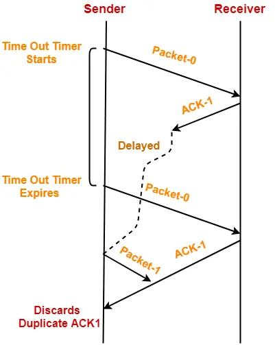


Role of Sequence Number on Acknowledgements


Consider the above example-


Step-01:


  • Sender sends a data packet with sequence number-0 to the receiver.


Step-02:


  • Receiver receives the data packet correctly.
  • Receiver now expects data packet with sequence number-1.
  • Receiver sends the acknowledgement ACK-1.


Step-03:


  • Acknowledgement ACK-1 sent by the receiver gets delayed in reaching the sender.


Step-04:


  • Sender receives no acknowledgement and time out occurs.
  • Sender retransmits the same data packet with sequence number-0.
  • This will be a duplicate packet for the receiver.


Step-05:


  • Receiver receives the data packet and discovers it is the duplicate packet.
  • It expects the data packet with sequence number-1 but receiving the data packet with sequence number-0.
  • It discards the duplicate data packet and re-sends acknowledgement ACK-1.
  • ACK-1 requests the sender to send a data packet with sequence number-1.


Step-06:


  • Two acknowledgements ACK1 reaches the sender.
  • When first acknowledgement ACK1 reaches the sender, sender sends the next data packet with sequence number 1.
  • When second acknowledgement ACK1 reaches the sender, sender rejects the duplicate acknowledgement.
  • This is because it has already sent the data packet with sequence number-1 and now sender expects the acknowledgement with sequence number 0 from the receiver.


Conclusion-


  • Had the sequence numbers not been allotted to the acknowledgements, sender would have accepted the duplicate acknowledgement thinking of it as the new acknowledgement for the latest data packet sent by it.
  • This is how sequence numbers allotted to the acknowledgements prove to be useful for identifying duplicate acknowledgements and discarding them.


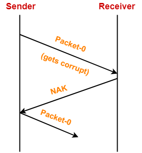
4. Problem of Damaged Packet-


  • If receiver receives a corrupted data packet from the sender, it sends a negative acknowledgement (NAK) to the sender.
  • NAK requests the sender to send the data packet again.


Stop and Wait Protocol Vs Stop and Wait ARQ-


The following comparison table states the differences between the two protocols-


Stop and Wait Protocol Stop and Wait ARQ
It assumes that the communication channel is perfect and noise free. It assumes that the communication channel is imperfect and noisy.
Data packet sent by the sender can never get corrupt. Data packet sent by the sender may get corrupt.
There is no concept of negative acknowledgements. A negative acknowledgement is sent by the receiver if the data packet is found to be corrupt.
There is no concept of time out timer. Sender starts the time out timer after sending the data packet.
There is no concept of sequence numbers. Data packets and acknowledgements are numbered using sequence numbers.


Limitation of Stop and Wait ARQ-


The major limitation of Stop and Wait ARQ is its very less efficiency.


To increase the efficiency, protocols like Go back N and Selective Repeat are used.


Explanation-


In stop and wait ARQ,

  • Sender window size is 1.
  • This allows the sender to keep only one frame unacknowledged.
  • So, sender sends one frame and then waits until the sent frame gets acknowledged.
  • After receiving the acknowledgement from the receiver, sender sends the next frame.
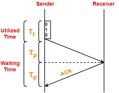


Here,

  • Sender uses Tt time for transmitting the packet over the link.
  • Then, sender waits for 2 x Tp time.
  • After 2 x Tp time, sender receives the acknowledgement for the sent frame from the receiver.
  • Then, sender sends the next frame.
  • This 2 x Tp waiting time is the actual cause of less efficiency.


Efficiency Improvement-


  • The efficiency of stop and wait ARQ can be improved by increasing the window size.
  • This allows the sender to keep more than one unacknowledged frame in its window.
  • Thus, sender can send frames in the waiting time too.

This gives rise to the concept of sliding window protocols.


To gain better understanding about Stop and Wait ARQ,

Watch this Video Lecture


Next Article- Practice Problems On Stop and Wait Protocol


Get more notes and other study material of Computer Networks.

Watch video lectures by visiting our YouTube channel LearnVidFun.
Flow Control | Stop and Wait Protocol

Flow Control in Computer Networks-


In computer networks, flow control is defined as-


A set of procedures which are used for restricting the amount of data that a sender can send to the receiver.


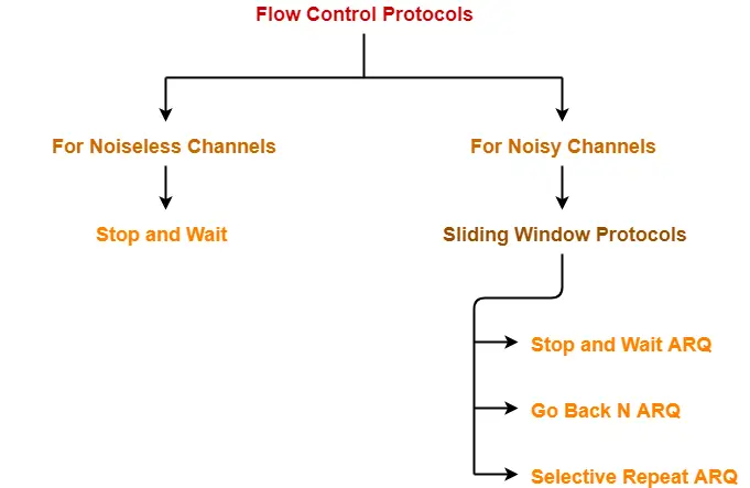
Flow Control Protocols-


There are various flow control protocols which are classified as-


In this article, we will discuss about stop and wait protocol.


Stop and Wait Protocol-


Stop and Wait Protocol is the simplest flow control protocol.


It works under the following assumptions-

  • Communication channel is perfect.
  • No error occurs during transmission.


Working-


The working of a stop and wait protocol may be explained as-

  • Sender sends a data packet to the receiver.
  • Sender stops and waits for the acknowledgement for the sent packet from the receiver.
  • Receiver receives and processes the data packet.
  • Receiver sends an acknowledgement to the sender.
  • After receiving the acknowledgement, sender sends the next data packet to the receiver.


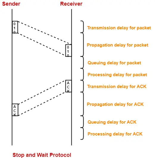
These steps are illustrated below-


Analysis-


Now, let us analyze in depth how the transmission is actually carried out-


  • Sender puts the data packet on the transmission link.
  • Data packet propagates towards the receiver’s end.
  • Data packet reaches the receiver and waits in its buffer.
  • Receiver processes the data packet.
  • Receiver puts the acknowledgement on the transmission link.
  • Acknowledgement propagates towards the sender’s end.
  • Acknowledgement reaches the sender and waits in its buffer.
  • Sender processes the acknowledgement.


These steps are illustrated below-


Also Read- Delays in Computer Networks


Total Time-


Total time taken in sending one data packet

= (Transmission delay + Propagation delay + Queuing delay + Processing delay)packet

+

(Transmission delay + Propagation delay + Queuing delay + Processing delay)ACK


Assume-

  • Queuing delay and processing delay to be zero at both sender and receiver side.
  • Transmission time for the acknowledgement to be zero since it’s size is very small.


Under the above assumptions.


Total time taken in sending one data packet

= (Transmission delay + Propagation delay)packet + (Propagation delay)ACK


We know,

  • Propagation delay depends on the distance and speed.
  • So, it would be same for both data packet and acknowledgement.


So, we have-


Total time taken in sending one data packet

= (Transmission delay)packet + 2 x Propagation delay


Efficiency-


Efficiency of any flow control control protocol is given by-


Efficiency (η) = Useful Time / Total Time


where-

  • Useful time = Transmission delay of data packet = (Transmission delay)packet
  • Useless time = Time for which sender is forced to wait and do nothing = 2 x Propagation delay
  • Total time = Useful time + Useless time


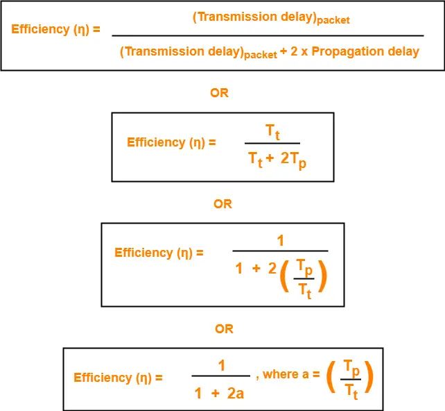
Thus,


Factors Affecting Efficiency-


We know,

Efficiency (η)

= (Transmission delay)packet / { (Transmission delay)packet + 2 x Propagation delay }


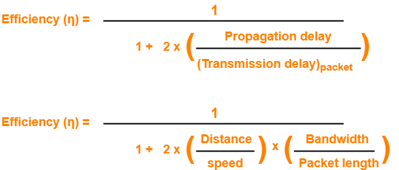
Dividing numerator and denominator by  (Transmission delay)packet, we get-


From here, we can observe-

  • Efficiency (η) ∝ 1 / Distance between sender and receiver
  • Efficiency (η) ∝ 1 / Bandwidth
  • Efficiency (η) ∝ Transmission speed
  • Efficiency (η) ∝ Length of data packet


Throughput-


  • Number of bits that can be sent through the channel per second is called as its throughput.


Round Trip Time-


Round Trip Time = 2 x Propagation delay


Advantages-


The advantages of stop and wait protocol are-

  • It is very simple to implement.
  • The incoming packet from receiver is always an acknowledgement.


Limitations-


The limitations of stop and wait protocol are-


Point-01:


It is extremely inefficient because-

  • It makes the transmission process extremely slow.
  • It does not use the bandwidth entirely as each single packet and acknowledgement uses the entire time to traverse the link.


Point-02:


If the data packet sent by the sender gets lost, then-

  • Sender will keep waiting for the acknowledgement for infinite time.
  • Receiver will keep waiting for the data packet for infinite time.


Point-03:


If acknowledgement sent by the receiver gets lost, then-

  • Sender will keep waiting for the acknowledgement for infinite time.
  • Receiver will keep waiting for another data packet for infinite time.


Important Notes-


Note-01:


Efficiency may also be referred by the following names-

  • Line Utilization
  • Link Utilization
  • Sender Utilization
  • Utilization of Sender


Note-02:


Throughput may also be referred by the following names-

  • Bandwidth Utilization
  • Effective Bandwidth
  • Maximum data rate possible
  • Maximum achievable throughput


Note-03:


Stop and Wait protocol performs better for LANs than WANs.

This is because-

  • Efficiency of the protocol is inversely proportional to the distance between sender and receiver.
  • So, the protocol performs better where the distance between sender and receiver is less.
  • The distance is less in LANs as compared to WANs.


To gain better understanding about Stop and Wait Protocol,

Watch this Video Lecture


Next Article- Stop and Wait ARQ


Get more notes and other study material of Computer Networks.

Watch video lectures by visiting our YouTube channel LearnVidFun.
Simplex | Half Duplex | Full Duplex

Types of Communication Channels-


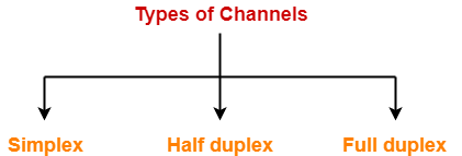
In computer networking, there are 3 types of communication channels-


  1. Simplex channel
  2. Half duplex channel
  3. Full duplex channel


1. Simplex Channel-


  • A simplex communication channel can send the signals only in one direction.
  • Thus, entire bandwidth of the channel can be used during the transmission.


Example-


Radio station

  • Radio station is a good example of a simplex communication channel.
  • A radio station always sends signals to its audience.
  • It never receives signals from the audience.


2. Half Duplex Channel-


  • A half duplex communication channel can send signals in both the directions but in only one direction at a time.
  • It may be considered as a simplex communication channel whose transmission direction can be switched.


Example-


Walkie-Talkie

  • Walkie-Talkie is a good example of a half duplex channel.
  • Walkie-talkie has a push-to-talk button.
  • This button is used to turn on the transmitter but turn off the receiver.
  • When the button is pressed, transmitter can not hear the receiver but receiver can hear the transmitter.


3. Full Duplex Channel-


  • A full duplex communication channel can send signals in both the directions at the same time.
  • Full duplex communication channels greatly increases the efficiency of communication.


Example-


Telephone

  • Telephone is a good example of a full duplex channel.
  • Both the persons can speak as well as hear each other at the same time.


Channel Capacity-


The total number of bits a channel can hold is called as its capacity.


Capacity of a half duplex channel

= Bandwidth x Propagation delay


Capacity of a full duplex channel

= 2 x Capacity of a half duplex channel

= 2 x Bandwidth x Propagation delay


To gain better understanding about communication channels in networking,

Watch this Video Lecture


Next Article- Stop and Wait Protocol


Get more notes and other study material of Computer Networks.

Watch video lectures by visiting our YouTube channel LearnVidFun.
Delays in Computer Networks | Formulas

Delays in Computer Networks-


Consider-

  • Two hosts A and B are connected over a transmission link / transmission media.
  • A data packet is sent by the Host A to Host B.


Following different types of delay occur during transmission-


  1. Transmission delay
  2. Propagation delay
  3. Queuing delay
  4. Processing delay


1. Transmission Delay-


Time taken to put the data packet on the transmission link is called as transmission delay.


Mathematically,

  • Transmission delay ∝ Length / Size of data packet
  • Transmission delay ∝ 1 / Bandwidth


Thus,


2. Propagation Delay-


Time taken for one bit to travel from sender to receiver end of the link is called as propagation delay.


Mathematically,

  • Propagation delay ∝ Distance between sender and receiver
  • Propagation delay ∝ 1 / transmission speed


Thus,


3. Queuing Delay-


Time spent by the data packet waiting in the queue before it is taken for execution is called as queuing delay.


  • It depends on the congestion in the network.


4. Processing Delay-


Time taken by the processor to process the data packet is called as processing delay.


  • It depends on the speed of the processor.
  • Processing of the data packet helps in detecting bit level errors that occurs during transmission.


Important Points-


Note-01:


Total delay in sending one data packet or End to End time

= Transmission delay + Propagation delay + Queuing delay + Processing delay


Note-02:


In optical fibre, transmission speed of data packet = 2.1 x 10⁸ m/sec


  • In optical fibre, signals travel with 70% speed of light.

70% speed of light

= 0.7 x 3 x 108 m/sec

= 2.1 x 108 m/sec

  • So, consider transmission speed = 2.1 x 10⁸ m/sec for calculations when using optical fibre.


Note-03:


Both queuing delay and processing delay are dependent on the state of the system.


This is because-

  • If destination host is busy doing some heavy processing, then these delays will increase.
  • If destination host is free, then data packets will be processed immediately and these delays will decrease.


Note-04:


  • For any particular transmission link, bandwidth and transmission speed are always constant.
  • This is because they are properties of the transmission medium.


Note-05:


Bandwidth is always expressed in powers of 10 and data is always expressed in powers of 2.

(Remember while solving numerical problems)


Examples-


  • 1 kilo bytes = 210 bytes
  • 1 kilo bits = 210 bits
  • 1 Mega bytes = 220 bytes
  • 1 kilo bytes per second = 103 bytes per second
  • 1 kilo bits per second = 103 bits per second
  • 1 Mega bytes per second = 106 bytes per second


To gain better understanding about delays in computer networks,

Watch this Video Lecture


Next Article- Types Of Channels in Computer Networks


Get more notes and other study material of Computer Networks.

Watch video lectures by visiting our YouTube channel LearnVidFun.
Subnet Mask | Subnet Mask Use

Subnet Mask-


Before you go through this article, make sure that you have gone through the previous article on Subnet Mask.


We have discussed-

  • Subnet mask is a 32 bit address consisting of a sequence of 1’s and 0’s.
  • It is used to determine to which subnet the given IP Address belongs to.


In this article, we will discuss how subnet mask is used by the host assigned to it.


Concept To Know-


When any host connects to the internet, ISP provides following 4 things to the host-

  1. IP Address
  2. Default Gateway
  3. Subnet Mask
  4. DNS


1. IP Address-


  • ISP assigns an IP Address to the host so that it can be uniquely identified on the Internet.


2. Default Gateway-


  • Default router connected to the network in which the host is present is the default gateway for the host.


3. Subnet Mask-


  • Subnet mask is a 32 bit number that is assigned to the host.
  • It is used to determine to which network the given IP Address belongs to.


4. Domain Name Service (DNS)-


Subnet Mask Use-


Subnet mask is used to determine to which network the given IP Address belongs to.


  • Host use its subnet mask to determine whether the other host it wants to communicate with is present within the same network or not.
  • If the destination host is present within the same network, then source host sends the packet directly to the destination host.
  • If the destination host is present in some other network, then source host routes the packet to the default gateway (router).
  • Router then sends the packet to the destination host.


Example-


Consider-

  • There is a host A present in some network X.
  • There is a host B.
  • Host A wants to send a packet to host B.


Before transmitting the packet, host A determines whether host B is present within the same network or not.


Here,

  • Host A = Source host
  • Host B = Destination host


To determine whether destination host is present within the same network or not, source host follows the following steps-


Step-01:


  • Source host computes its own network address using its own IP Address and subnet mask.
  • After computation, source host obtains its network address with respect to itself.


Step-02:


  • Source host computes the network address of destination host using destination IP Address and its own subnet mask.
  • After computation, source host obtains the network address of destination host with respect to itself.


Step-03:


Source host compares the two results obtained in the above steps.

Then, following two cases are possible-


Case-01:


If the results are same,

  • Source host assumes that the destination host is present within the same network.
  • Source host sends the packet directly to the destination host.


Case-02:


If the results are different,

  • Source host assumes that the destination host is present in some other network.
  • Source host sends the packet via router to the destination host.


Important Points-


Note-01:


  • Each host knows only its own subnet mask.
  • It does not know the subnet mask of any other host.


Note-02:


  • The conclusion drawn by a host about the presence of other host within the same or different network might be wrong.


Note-03:


  • Consider host A draws some conclusion about host B.
  • Then, same conclusion might not be drawn by host B about host A.
  • Both the hosts have to perform the above procedure separately at their ends to conclude anything.


PRACTICE PROBLEMS BASED ON USE OF SUBNET MASK-


Problem-01:


Two computers C1 and C2 are configured as follows-

  • C1 has IP Address 203.197.2.53 and net mask 255.255.128.0
  • C2 has IP Address 203.197.75.201 and net mask 255.255.192.0


Which one of the following statements is true?

  1. C1 and C2 both assume they are on the same network
  2. C2 assumes C1 is on same network but C1 assumes C2 is on a different network
  3. C1 assumes C2 is on same network but C2 assumes C1 is on a different network
  4. C1 and C2 both assume they are on different networks


Solution-


At Computer C1-


C1 computes its network address using its own IP Address and subnet mask as-

203.197.2.53 AND 255.255.128.0

= 203.197.0.0


C1 computes the network address of C2 using IP Address of C2 and its own subnet mask as-

203.197.75.201 AND 255.255.128.0

= 203.197.0.0


Since both the results are same, so C1 assumes that C2 is on the same network.


At Computer C2-


C2 computes its network address using its own IP Address and subnet mask as-

203.197.75.201 AND 255.255.192.0

= 203.197.64.0


C2 computes the network address of C1 using IP Address of C1 and its own subnet mask as-

203.197.2.53 AND 255.255.192.0

= 203.197.0.0


Since both the results are different, so C2 assumes that C1 is on a different network.

Thus, Option (C) is correct.


Problem-02:


The subnet mask for a particular network is 255.255.31.0. Which of the following pairs of IP Addresses could belong to this network?

  1. 172.57.88.62 and 172.56.87.233
  2. 10.35.28.2 and 10.35.29.4
  3. 191.203.31.87 and 191.234.31.88
  4. 128.8.129.43 and 128.8.161.55


Solution-


Let the given two IP Addresses belong to Host A and Host B.


Checking Option (A)-


  • Host A IP Address = 172.57.88.62
  • Host B IP Address = 172.56.87.233


At Host A-


Host A computes its network address using its own IP Address and subnet mask-

172.57.88.62 AND 255.255.31.0

= 172.57.24.0


Host A computes the network address of Host B using IP Address of Host B and its own subnet mask-

172.56.87.233 AND 255.255.31.0

= 172.56.23.0


Since both the results are different, so host A assumes that host B is on a different network.

Thus, both can’t belong to the same network.

Hence, this option gets eliminated.


Checking Option (B)-


  • Host A IP Address = 10.35.28.2
  • Host B IP Address = 10.35.29.4


At Host A-


Host A computes its network address using its own IP Address and subnet mask-

10.35.28.2 AND 255.255.31.0

= 10.35.28.0


Host A computes the network address of Host B using IP Address of Host B and its own subnet mask-

10.35.29.4 AND 255.255.31.0

= 10.35.29.0


Since both the results are different, so host A assumes that host B is on a different network.

Thus, both can’t belong to the same network.

Hence, this option gets eliminated.


Checking Option (C)-


  • Host A IP Address = 191.203.31.87
  • Host B IP Address = 191.234.31.88


At Host A-


Host A computes its network address using its own IP Address and subnet mask-

191.203.31.87 AND 255.255.31.0

= 191.203.31.0


Host A computes the network address of Host B using IP Address of Host B and its own subnet mask-

191.234.31.88 AND 255.255.31.0

= 191.234.31.0


Since both the results are same, so host A assumes that host B is on the same network.


At Host B-


Host B computes its network address using its own IP Address and subnet mask-

191.234.31.88 AND 255.255.31.0

= 191.234.31.0


Host B computes the network address of Host A using IP Address of Host A and its own subnet mask-

191.203.31.87 AND 255.255.31.0

= 191.203.31.0


Since both the results are different, so host B assumes that host A is on a different network.

Thus, both can’t belong to the same network.

Hence, this option gets eliminated.


Checking Option (D)-


  • Host A IP Address = 128.8.129.43
  • Host B IP Address = 128.8.161.55


At Host A-


Host A computes its network address using its own IP Address and subnet mask-

128.8.129.43 AND 255.255.31.0

= 128.8.1.0


Host A computes the network address of Host B using IP Address of Host B and its own subnet mask-

128.8.161.55 AND 255.255.31.0

= 128.8.1.0


Since both the results are same, so host A assumes that host B is on the same network.


At Host B-


Host B computes its network address using its own IP Address and subnet mask-

128.8.161.55 AND 255.255.31.0

= 128.8.1.0


Host B computes the network address of Host A using IP Address of Host A and its own subnet mask-

128.8.129.43 AND 255.255.31.0

= 128.8.1.0


Since both the results are same, so host B assumes that host A is on the same network.

Thus, both the hosts assume that they belong to the same network.

Hence, Option (D) is correct.


To gain better understanding about Subnet Mask Use,

Watch this Video Lecture


Next Article- Internet Protocol Version 4 | IPv4 Header


Get more notes and other study material of Computer Networks.

Watch video lectures by visiting our YouTube channel LearnVidFun.