Tag: Basics of Computer Networks

TCP Congestion Control | Congestion in Network

Congestion in Network-


Congestion refers to a network state where-

The message traffic becomes so heavy that it slows down the network response time.


  • Congestion is an important issue that can arise in Packet Switched Network.
  • Congestion leads to the loss of packets in transit.
  • So, it is necessary to control the congestion in network.
  • It is not possible to completely avoid the congestion.


Congestion Control-


Congestion control refers to techniques and mechanisms that can-

  • Either prevent congestion before it happens
  • Or remove congestion after it has happened


Now, let us discuss how congestion is handled at TCP.


TCP Congestion Control-


TCP reacts to congestion by reducing the sender window size.


The size of the sender window is determined by the following two factors-

  1. Receiver window size
  2. Congestion window size


1. Receiver Window Size-


Receiver window size is an advertisement of-

“How much data (in bytes) the receiver can receive without acknowledgement?”


  • Sender should not send data greater than receiver window size.
  • Otherwise, it leads to dropping the TCP segments which causes TCP Retransmission.
  • So, sender should always send data less than or equal to receiver window size.
  • Receiver dictates its window size to the sender through TCP Header.


2. Congestion Window-


  • Sender should not send data greater than congestion window size.
  • Otherwise, it leads to dropping the TCP segments which causes TCP Retransmission.
  • So, sender should always send data less than or equal to congestion window size.
  • Different variants of TCP use different approaches to calculate the size of congestion window.
  • Congestion window is known only to the sender and is not sent over the links.


So, always-


Sender window size = Minimum (Receiver window size, Congestion window size)


TCP Congestion Policy-


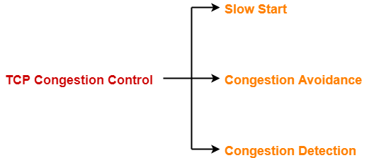
TCP’s general policy for handling congestion consists of following three phases-


  1. Slow Start
  2. Congestion Avoidance
  3. Congestion Detection


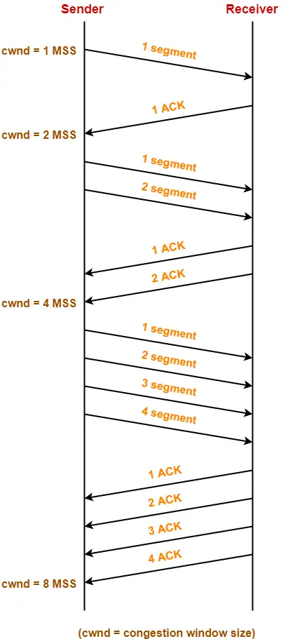
1. Slow Start Phase-


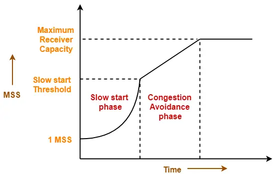
  • Initially, sender sets congestion window size = Maximum Segment Size (1 MSS).
  • After receiving each acknowledgment, sender increases the congestion window size by 1 MSS.
  • In this phase, the size of congestion window increases exponentially.


The followed formula is-


Congestion window size = Congestion window size + Maximum segment size


This is shown below-


  • After 1 round trip time, congestion window size = (2)1 = 2 MSS
  • After 2 round trip time, congestion window size = (2)2 = 4 MSS
  • After 3 round trip time, congestion window size = (2)3 = 8 MSS and so on.


This phase continues until the congestion window size reaches the slow start threshold.


Threshold

= Maximum number of TCP segments that receiver window can accommodate / 2

= (Receiver window size / Maximum Segment Size) / 2


2. Congestion Avoidance Phase-


After reaching the threshold,

  • Sender increases the congestion window size linearly to avoid the congestion.
  • On receiving each acknowledgement, sender increments the congestion window size by 1.


The followed formula is-


Congestion window size = Congestion window size + 1


This phase continues until the congestion window size becomes equal to the receiver window size.


3. Congestion Detection Phase-


When sender detects the loss of segments, it reacts in different ways depending on how the loss is detected-


Case-01: Detection On Time Out-


  • Time Out Timer expires before receiving the acknowledgement for a segment.
  • This case suggests the stronger possibility of congestion in the network.
  • There are chances that a segment has been dropped in the network.


Reaction-


In this case, sender reacts by-

  • Setting the slow start threshold to half of the current congestion window size.
  • Decreasing the congestion window size to 1 MSS.
  • Resuming the slow start phase.


Case-02: Detection On Receiving 3 Duplicate Acknowledgements-


  • Sender receives 3 duplicate acknowledgements for a segment.
  • This case suggests the weaker possibility of congestion in the network.
  • There are chances that a segment has been dropped but few segments sent later may have reached.


Reaction-


In this case, sender reacts by-

  • Setting the slow start threshold to half of the current congestion window size.
  • Decreasing the congestion window size to slow start threshold.
  • Resuming the congestion avoidance phase.


Next Article- Practice Problems On TCP Congestion Control


Get more notes and other study material of Computer Networks.

Watch video lectures by visiting our YouTube channel LearnVidFun.

TCP Header | TCP Header Format | TCP Flags

Transmission Control Protocol-


Before you go through this article, make sure that you have gone through the previous article on TCP in Networking.


We have discussed-

  • Transmission Control Protocol is a transport layer protocol.
  • It continuously receives data from the application layer.
  • It divides the data into chunks where each chunk is a collection of bytes.
  • It then creates TCP segments by adding a TCP header to the data chunks.
  • TCP segments are encapsulated in the IP datagram.


TCP segment = TCP header + Data chunk


In this article, we will discuss about TCP Header.


TCP Header-


The following diagram represents the TCP header format-
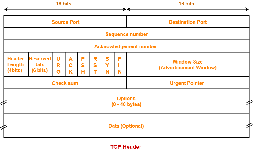


Let us discuss each field of TCP header one by one.


1. Source Port-


  • Source Port is a 16 bit field.
  • It identifies the port of the sending application.


2. Destination Port-


  • Destination Port is a 16 bit field.
  • It identifies the port of the receiving application.


NOTE

It is important to note-

  • A TCP connection is uniquely identified by using-

Combination of port numbers and IP Addresses of sender and receiver

  • IP Addresses indicate which systems are communicating.
  • Port numbers indicate which end to end sockets are communicating.


3. Sequence Number-


  • Sequence number is a 32 bit field.
  • TCP assigns a unique sequence number to each byte of data contained in the TCP segment.
  • This field contains the sequence number of the first data byte.


4. Acknowledgement Number-


  • Acknowledgment number is a 32 bit field.
  • It contains sequence number of the data byte that receiver expects to receive next from the sender.
  • It is always sequence number of the last received data byte incremented by 1.


5. Header Length-


  • Header length is a 4 bit field.
  • It contains the length of TCP header.
  • It helps in knowing from where the actual data begins.


Minimum and Maximum Header length-


The length of TCP header always lies in the range-

[20 bytes , 60 bytes]


  • The initial 5 rows of the TCP header are always used.
  • So, minimum length of TCP header = 5 x 4 bytes = 20 bytes.
  • The size of the 6th row representing the Options field vary.
  • The size of Options field can go up to 40 bytes.
  • So, maximum length of TCP header = 20 bytes + 40 bytes = 60 bytes.


Concept of Scaling Factor-


  • Header length is a 4 bit field.
  • So, the range of decimal values that can be represented is [0, 15].
  • But the range of header length is [20, 60].
  • So, to represent the header length, we use a scaling factor of 4.


In general,


Header length = Header length field value x 4 bytes


Examples-


  • If header length field contains decimal value 5 (represented as 0101), then-

Header length = 5 x 4 = 20 bytes

  • If header length field contains decimal value 10 (represented as 1010), then-

Header length = 10 x 4 = 40 bytes

  • If header length field contains decimal value 15 (represented as 1111), then-

Header length = 15 x 4 = 60 bytes


NOTES

It is important to note-

  • Header length and Header length field value are two different things.
  • The range of header length field value is always [5, 15].
  • The range of header length is always [20, 60].


While solving questions-

  • If the given value lies in the range [5, 15] then it must be the header length field value.
  • This is because the range of header length is always [20, 60].


6. Reserved Bits-


  • The 6 bits are reserved.
  • These bits are not used.


7. URG Bit-


URG bit is used to treat certain data on an urgent basis.


When URG bit is set to 1,

  • It indicates the receiver that certain amount of data within the current segment is urgent.
  • Urgent data is pointed out by evaluating the urgent pointer field.
  • The urgent data has be prioritized.
  • Receiver forwards urgent data to the receiving application on a separate channel.


8. ACK Bit-


ACK bit indicates whether acknowledgement number field is valid or not.


  • When ACK bit is set to 1, it indicates that acknowledgement number contained in the TCP header is valid.
  • For all TCP segments except request segment, ACK bit is set to 1.
  • Request segment is sent for connection establishment during Three Way Handshake.


9. PSH Bit-


PSH bit is used to push the entire buffer immediately to the receiving application.


When PSH bit is set to 1,

  • All the segments in the buffer are immediately pushed to the receiving application.
  • No wait is done for filling the entire buffer.
  • This makes the entire buffer to free up immediately.


NOTE

It is important to note-

  • Unlike URG bit, PSH bit does not prioritize the data.
  • It just causes all the segments in the buffer to be pushed immediately to the receiving application.
  • The same order is maintained in which the segments arrived.
  • It is not a good practice to set PSH bit = 1.
  • This is because it disrupts the working of receiver’s CPU and forces it to take an action immediately.


10. RST Bit-


RST bit is used to reset the TCP connection.


When RST bit is set to 1,

  • It indicates the receiver to terminate the connection immediately.
  • It causes both the sides to release the connection and all its resources abnormally.
  • The transfer of data ceases in both the directions.
  • It may result in the loss of data that is in transit.


This is used only when-

  • There are unrecoverable errors.
  • There is no chance of terminating the TCP connection normally.


11. SYN Bit-


SYN bit is used to synchronize the sequence numbers.


When SYN bit is set to 1,

  • It indicates the receiver that the sequence number contained in the TCP header is the initial sequence number.
  • Request segment sent for connection establishment during Three way handshake contains SYN bit set to 1.


12. FIN Bit-


FIN bit is used to terminate the TCP connection.


When FIN bit is set to 1,

  • It indicates the receiver that the sender wants to terminate the connection.
  • FIN segment sent for TCP Connection Termination contains FIN bit set to 1.


13. Window Size-


  • Window size is a 16 bit field.
  • It contains the size of the receiving window of the sender.
  • It advertises how much data (in bytes) the sender can receive without acknowledgement.
  • Thus, window size is used for Flow Control.


NOTE

It is important to note-

  • The window size changes dynamically during data transmission.
  • It usually increases during TCP transmission up to a point where congestion is detected.
  • After congestion is detected, the window size is reduced to avoid having to drop packets.


14. Checksum-


  • Checksum is a 16 bit field used for error control.
  • It verifies the integrity of data in the TCP payload.
  • Sender adds CRC checksum to the checksum field before sending the data.
  • Receiver rejects the data that fails the CRC check.


Also Read- CRC | Checksum


15. Urgent Pointer-


  • Urgent pointer is a 16 bit field.
  • It indicates how much data in the current segment counting from the first data byte is urgent.
  • Urgent pointer added to the sequence number indicates the end of urgent data byte.
  • This field is considered valid and evaluated only if the URG bit is set to 1.


USEFUL FORMULAS


Formula-01:

Number of urgent bytes = Urgent pointer + 1


Formula-02:

End of urgent byte

= Sequence number of the first byte in the segment + Urgent pointer


16. Options-


  • Options field is used for several purposes.
  • The size of options field vary from 0 bytes to 40 bytes.


Options field is generally used for the following purposes-

  1. Time stamp
  2. Window size extension
  3. Parameter negotiation
  4. Padding


A. Time Stamp-


When wrap around time is less than life time of a segment,

  • Multiple segments having the same sequence number may appear at the receiver side.
  • This makes it difficult for the receiver to identify the correct segment.
  • If time stamp is used, it marks the age of TCP segments.
  • Based on the time stamp, receiver can identify the correct segment.


B. Window Size Extension-


  • Options field may be used to represent a window size greater than 16 bits.
  • Using window size field of TCP header, window size of only 16 bits can be represented.
  • If the receiver wants to receive more data, it can advertise its greater window size using this field.
  • The extra bits are then appended in Options field.


C. Parameter Negotiation-


Options field is used for parameters negotiation.

Example- During connection establishment,

  • Both sender and receiver have to specify their maximum segment size.
  • To specify maximum segment size, there is no special field.
  • So, they specify their maximum segment size using this field and negotiates.


D. Padding-


  • Addition of dummy data to fill up unused space in the transmission unit and make it conform to the standard size is called as padding.
  • Options field is used for padding.


Example-


  • When header length is not a multiple of 4, extra zeroes are padded in the Options field.
  • By doing so, header length becomes a multiple of 4.
  • If header length = 30 bytes, 2 bytes of dummy data is added to the header.
  • This makes header length = 32 bytes.
  • Then, the value 32 / 4 = 8 is put in the header length field.
  • In worst case, 3 bytes of dummy data might have to be padded to make the header length a multiple of 4.


Also Read- IPv4 Header | UDP Header


To gain better understanding about TCP Header,

Watch this Video Lecture


Next Article- TCP Sequence Number | Wrap Around Time


Get more notes and other study material of Computer Networks.

Watch video lectures by visiting our YouTube channel LearnVidFun.
3 Way Handshake | TCP Connection

Transmission Control Protocol-


Before you go through this article, make sure that you have gone through the previous article on TCP in Networking.


We have discussed-

  • TCP establishes an end to end connection between the sender and receiver.
  • This connection is established before exchanging the data.
  • TCP connection is reliable and ensures in order delivery.


Also Read- TCP Header


In this article, we will discuss how a TCP connection is established.


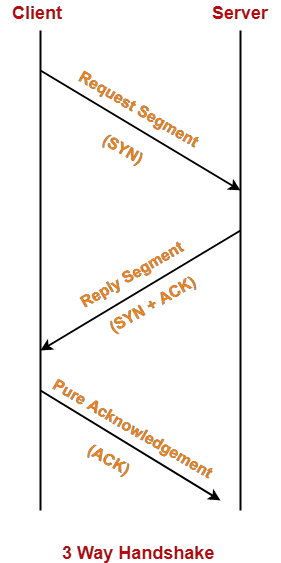
3 Way Handshake-


Three Way Handshake is a process used for establishing a TCP connection.


Consider-

  • Client wants to establish a connection with the server.
  • Before Three Way Handshake, both client and server are in closed state.


TCP Handshake involves the following steps in establishing the connection-


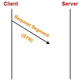
Step-01: SYN-


For establishing a connection,

  • Client sends a request segment to the server.
  • Request segment consists only of TCP Header with an empty payload.
  • Then, it waits for a reply segment from the server.


Request segment contains the following information in TCP header-

  1. Initial sequence number
  2. SYN bit set to 1
  3. Maximum segment size
  4. Receiving window size


1. Initial Sequence Number-


  • Client sends the initial sequence number to the server.
  • It is contained in the sequence number field.
  • It is a randomly chosen 32 bit value.


2. SYN Bit Set To 1-


Client sets SYN bit to 1 which indicates the server-

  • This segment contains the initial sequence number used by the client.
  • It has been sent for synchronizing the sequence numbers.


Also Read- TCP Sequence Number


3. Maximum Segment Size (MSS)-


  • Client sends its MSS to the server.
  • It dictates the size of the largest data chunk that client can send and receive from the server.
  • It is contained in the Options field.


4. Receiving Window Size-


  • Client sends its receiving window size to the server.
  • It dictates the limit of unacknowledged data that can be sent to the client.
  • It is contained in the window size field.


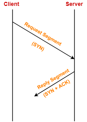
Step-02: SYN + ACK-


After receiving the request segment,

  • Server responds to the client by sending the reply segment.
  • It informs the client of the parameters at the server side.


Reply segment contains the following information in TCP header-

  1. Initial sequence number
  2. SYN bit set to 1
  3. Maximum segment size
  4. Receiving window size
  5. Acknowledgment number
  6. ACK bit set to 1


1. Initial Sequence Number-


  • Server sends the initial sequence number to the client.
  • It is contained in the sequence number field.
  • It is a randomly chosen 32 bit value.


2. SYN Bit Set To 1-


Server sets SYN bit to 1 which indicates the client-

  • This segment contains the initial sequence number used by the server.
  • It has been sent for synchronizing the sequence numbers.


3. Maximum Segment Size (MSS)-


  • Server sends its MSS to the client.
  • It dictates the size of the largest data chunk that server can send and receive from the client.
  • It is contained in the Options field.


4. Receiving Window Size-


  • Server sends its receiving window size to the client.
  • It dictates the limit of unacknowledged data that can be sent to the server.
  • It is contained in the window size field.


5. Acknowledgement Number-


  • Server sends the initial sequence number incremented by 1 as an acknowledgement number.
  • It dictates the sequence number of the next data byte that server expects to receive from the client.


6. ACK Bit Set To 1-


  • Server sets ACK bit to 1.
  • It indicates the client that the acknowledgement number field in the current segment is valid.


Step-03: ACK-


After receiving the reply segment,

  • Client acknowledges the response of server.
  • It acknowledges the server by sending a pure acknowledgement.


With these, a Full Duplex connection is established.


Important Points-


Point-01:


In step-01 and step-02-

  • The connection parameters are established for the first side.
  • They are acknowledged by the second side.


In step-02 and step-03-

  • The connection parameters are established for the second side.
  • They are acknowledged by the first side.


Point-02:


Connection establishment phase consume 1 sequence number of both the sides.


  • Request segment consumes 1 sequence number of the requester.
  • Reply segment consumes 1 sequence number of the respondent.
  • Pure acknowledgements do not consume any sequence number.


Point-03:


Pure acknowledgement for the reply segment is not necessary.


This is because-

  • If client sends the data packet immediately, then it will be considered as an acknowledgement.
  • It means that in the first two steps only, the full duplex connection is established.


Point-04:


For all the segments except the request segment, ACK bit is always set to 1.


This is because-

  • For the request segment, acknowledgement number field will always be invalid.
  • For all other segments, acknowledgement number field will always be valid.


Point-05:


Certain parameters are negotiated during connection establishment.


The negotiation can be on setting the values of following parameters-

  1. Window size
  2. Maximum segment size
  3. Timer values


Point-06:


In any TCP segment,

  • If SYN bit = 1 and ACK bit = 0, then it must be the request segment.
  • If SYN bit = 1 and ACK bit = 1, then it must be the reply segment.
  • If SYN bit = 0 and ACK bit = 1, then it can be the pure ACK or segment meant for data transfer.
  • If SYN bit = 0 and ACK bit = 0, then this combination is not possible.


Point-07:


  • The combination SYN bit = 0 and ACK bit = 0 is not possible.
  • It is because SYN bit = 0 signifies it is not the request segment and reply segment.
  • For all other segments, ACK bit is always set to 1.


Point-08:


  • Consider sender sends the segments of size greater than MSS of receiver.
  • Then, they are first fragmented first at the receiver side.
  • It causes an extra overhead.


Point-09:


  • There is no dedicated field for sending MSS in TCP header.
  • This is because MSS has to informed only once.
  • So, if dedicated field would be present, then sending it each time would not be required.
  • For this reason, MSS is informed once using Options field.


Also Read- TCP Connection Termination


PRACTICE PROBLEMS BASED ON THREE WAY HANDSHAKE-


Problem-01:


SYN = 0 and ACK = 1 indicates-

  1. Open connection packet
  2. Open connection ACK
  3. Data packet
  4. ACK packet


Solution-


Options (C) and (D) are correct.


Problem-02:


An acknowledgement by TCP sender guarantees-

  1. Data has been delivered to the application
  2. Data has been received by TCP module
  3. Data has been received by application interface
  4. None of the above


Solution-


Option (A) is correct.


To gain better understanding about Three Way Handshake,

Watch this Video Lecture


Next Article- TCP Retransmission


Get more notes and other study material of Computer Networks.

Watch video lectures by visiting our YouTube channel LearnVidFun.
TCP Connection Termination | FIN Segment

Three Way Handshake-


Before you go through this article, make sure that you have gone through the previous article on Three Way Handshake.


We have discussed-

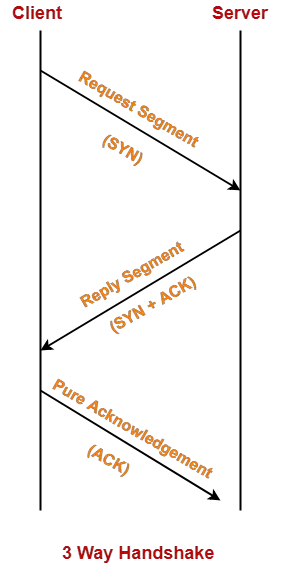
  • TCP uses Three Way Handshake to establish a connection between the sender and receiver.
  • Connection establishment using Three Way Handshake involves the steps as shown-


Also Read- TCP Retransmission


In this article, we will discuss how a TCP connection is terminated.


TCP Connection Termination-


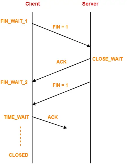
A TCP connection is terminated using FIN segment where FIN bit is set to 1.


Consider-

  • There is a well established TCP connection between the client and server.
  • Client wants to terminate the connection.


The following steps are followed in terminating the connection-


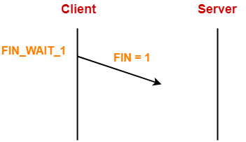
Step-01:


For terminating the connection,

  • Client sends a FIN segment to the server with FIN bit set to 1.
  • Client enters the FIN_WAIT_1 state.
  • Client waits for an acknowledgement from the server.


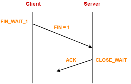
Step-02:


After receiving the FIN segment,

  • Server frees up its buffers.
  • Server sends an acknowledgement to the client.
  • Server enters the CLOSE_WAIT state.


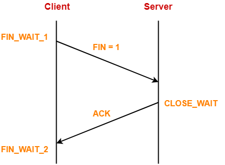
Step-03:


After receiving the acknowledgement, client enters the FIN_WAIT_2 state.


Now,

  • The connection from client to server is terminated i.e. one way connection is closed.
  • Client can not send any data to the server since server has released its buffers.
  • Pure acknowledgements can still be sent from the client to server.
  • The connection from server to client is still open i.e. one way connection is still open.
  • Server can send both data and acknowledgements to the client.


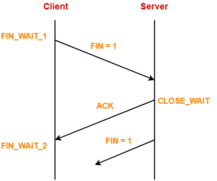
Step-04:


Now, suppose server wants to close the connection with the client.


For terminating the connection,

  • Server sends a FIN segment to the client with FIN bit set to 1.
  • Server waits for an acknowledgement from the client.


NOTE

If server wanted,

It could have sent the FIN segment along with the previous acknowledgment that it sent to the client.


Step-05:


After receiving the FIN segment,

  • Client frees up its buffers.
  • Client sends an acknowledgement to the server (not mandatory).
  • Client enters the TIME_WAIT state.


TIME_WAIT State-


  • The TIME_WAIT state allows the client to resend the final acknowledgement if it gets lost.
  • The time spent by the client in TIME_WAIT state depends on the implementation.
  • The typical values are 30 seconds, 1 minute and 2 minutes.
  • After the wait, the connection gets formally closed.


Next Article- Practice Problems On TCP


Get more notes and other study material of Computer Networks.

Watch video lectures by visiting our YouTube channel LearnVidFun.
TCP in Networking | TCP Protocol

Transport Layer Protocols-


There are mainly two transport layer protocols that are used on the Internet-


  1. Transmission Control Protocol (TCP)
  2. User Datagram Protocol (UDP)


In this article, we will discuss about Transmission Control Protocol (TCP).

Learn about User Datagram Protocol.


Transmission Control Protocol-


  • TCP is short for Transmission Control Protocol.
  • It is a transport layer protocol.
  • It has been designed to send data packets over the Internet.
  • It establishes a reliable end to end connection before sending any data.


Characteristics Of TCP-


Point-01:


TCP is a reliable protocol.


This is because-

  • It guarantees the delivery of data packets to its correct destination.
  • After receiving the data packet, receiver sends an acknowledgement to the sender.
  • It tells the sender whether data packet has reached its destination safely or not.
  • TCP employs retransmission to compensate for packet loss.


Read More- TCP Retransmission


Point-02:


TCP is a connection oriented protocol.


This is because-

  • TCP establishes an end to end connection between the source and destination.
  • The connection is established before exchanging the data.
  • The connection is maintained until the application programs at each end finishes exchanging the data.


Point-03:


TCP handles both congestion and flow control.


  • TCP handles congestion and flow control by controlling the window size.
  • TCP reacts to congestion by reducing the sender window size.


Read More- TCP Congestion Control


Point-04:


TCP ensures in-order delivery.


  • TCP ensures that the data packets get deliver to the destination in the same order they are sent by the sender.
  • Sequence Numbers are used to coordinate which data has been transmitted and received.


Point-05:


TCP connections are full duplex.


  • TCP connection allows to send data in both the directions at the same time.
  • So, TCP connections are Full Duplex.


Point-06:


TCP works in collaboration with Internet Protocol.


  • A TCP connection is uniquely identified by using-

Combination of port numbers and IP Addresses of sender and receiver.

  • IP Addresses indicate which systems are communicating.
  • Port numbers indicate which end to end sockets are communicating.
  • Port numbers are contained in the TCP header and IP Addresses are contained in the IP header.
  • TCP segments are encapsulated into an IP datagram.
  • So, TCP header immediately follows the IP header during transmission.


Point-07:


TCP can use both selective & cumulative acknowledgements.


  • TCP uses a combination of Selective Repeat and Go back N protocols.
  • In TCP, sender window size = receiver window size.
  • In TCP, out of order packets are accepted by the receiver.
  • When receiver receives an out of order packet, it accepts that packet but sends an acknowledgement for the expected packet.
  • Receiver may choose to send independent acknowledgements or cumulative acknowledgement.
  • To sum up, TCP is a combination of 75% SR protocol and 25% Go back N protocol.


Point-08:


TCP is a byte stream protocol.


  • Application layer sends data to the transport layer without any limitation.
  • TCP divides the data into chunks where each chunk is a collection of bytes.
  • Then, it creates a TCP segment by adding IP header to the data chunk.
  • TCP segment = TCP header + Data chunk.


Point-09:


TCP provides error checking & recovery mechanism.


TCP provides error checking and recovery using three simple techniques-

  1. Checksum
  2. Acknowledgement
  3. Retransmission


Also Read- Checksum


To gain better understanding about Transmission Control Protocol,

Watch this Video Lecture


Next Article- TCP Header


Get more notes and other study material of Computer Networks.

Watch video lectures by visiting our YouTube channel LearnVidFun.