Tag: Basics of Computer Networks

IP Fragmentation | Fragmentation in Networking

IP Fragmentation-


  • IP Fragmentation is a process of dividing the datagram into fragments during its transmission.
  • It is done by intermediary devices such as routers at the destination host at network layer.


Need-


  • Each network has its maximum transmission unit (MTU).
  • It dictates the maximum size of the packet that can be transmitted through it.
  • Data packets of size greater than MTU can not be transmitted through the network.
  • So, datagrams are divided into fragments of size less than or equal to MTU.


Datagram Fragmentation-


When router receives a datagram to transmit further, it examines the following-

  • Size of the datagram
  • MTU of the destination network
  • DF bit value in the IP header


Then, following cases are possible-


Case-01:


  • Size of the datagram is found to be smaller than or equal to MTU.
  • In this case, router transmits the datagram without any fragmentation.


Case-02:


  • Size of the datagram is found to be greater than MTU and DF bit set to 1.
  • In this case, router discards the datagram.


Case-03:


  • Size of the datagram is found to be greater than MTU and DF bit set to 0.
  • In this case, router divides the datagram into fragments of size less than or equal to MTU.
  • Router attaches an IP header with each fragment making the following changes in it.
  • Then, router transmits all the fragments of the datagram.


Changes Made By Router-


Router makes the following changes in IP header of each fragment-

  • It changes the value of total length field to the size of fragment.
  • It sets the MF bit to 1 for all the fragments except the last one.
  • For the last fragment, it sets the MF bit to 0.
  • It sets the fragment offset field value.
  • It recalculates the header checksum.


Also Read- IPv4 Header


IP Fragmentation Examples-


Now, lets us discuss some examples of IP fragmentation to understand how the fragmentation is actually carried out.


Example-01:


Consider-

  • There is a host A present in network X having MTU = 520 bytes.
  • There is a host B present in network Y having MTU = 200 bytes.
  • Host A wants to send a message to host B.


Consider router receives a datagram from host A having-

  • Header length = 20 bytes
  • Payload length = 500 bytes
  • Total length = 520 bytes
  • DF bit set to 0


Now, router works in the following steps-


Step-01:


Router examines the datagram and finds-

  • Size of the datagram = 520 bytes
  • Destination is network Y having MTU = 200 bytes
  • DF bit is set to 0


Router concludes-

  • Size of the datagram is greater than MTU.
  • So, it will have to divide the datagram into fragments.
  • DF bit is set to 0.
  • So, it is allowed to create fragments of the datagram.


Step-02:


Router decides the amount of data that it should transmit in each fragment.


Router knows-

  • MTU of the destination network = 200 bytes.
  • So, maximum total length of any fragment can be only 200 bytes.
  • Out of 200 bytes, 20 bytes will be taken by the header.
  • So, maximum amount of data that can be sent in any fragment = 180 bytes.


Router uses the following rule to choose the amount of data that will be transmitted in one fragment-


RULE


The amount of data sent in one fragment is chosen such that-

  • It is as large as possible but less than or equal to MTU.
  • It is a multiple of 8 so that pure decimal value can be obtained for the fragment offset field.


NOTE


  • It is not compulsory for the last fragment to contain the amount of data that is a multiple of 8.
  • This is because it does not have to decide the fragment offset value for any other fragment.


Following the above rule,

  • Router decides to send maximum 176 bytes of data in one fragment.
  • This is because it is the greatest value that is a multiple of 8 and less than MTU.


Step-03:


Router creates three fragments of the original datagram where-

  • First fragment contains the data = 176 bytes
  • Second fragment contains the data = 176 byes
  • Third fragment contains the data = 148 bytes
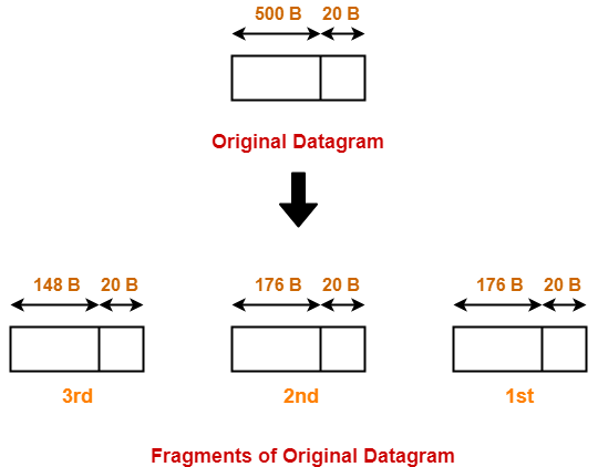


The information contained in the IP header of each fragment is-


Header Information Of 1st Fragment-


  • Header length field value = 20 / 4 = 5
  • Total length field value = 176 + 20 = 196
  • MF bit = 1
  • Fragment offset field value = 0
  • Header checksum is recalculated.
  • Identification number is same as that of original datagram.


Header Information Of 2nd Fragment-


  • Header length field value = 20 / 4 = 5
  • Total length field value = 176 + 20 = 196
  • MF bit = 1
  • Fragment offset field value = 176 / 8 = 22
  • Header checksum is recalculated.
  • Identification number is same as that of original datagram.


Header Information Of 3rd Fragment-


  • Header length field value = 20 / 4 = 5
  • Total length field value = 148 + 20 = 168
  • MF bit = 0
  • Fragment offset field value = (176 + 176) / 8 = 44
  • Header checksum is recalculated.
  • Identification number is same as that of original datagram.


Router transmits all the fragments.


Step-04:


At destination side,

  • Receiver receives 3 fragments of the datagram.
  • Reassembly algorithm is applied to combine all the fragments to obtain the original datagram.


Example-02:


Consider-

  • There is a host A present in network X having MTU = 520 bytes.
  • There is a host B present in network Y having MTU = 200 bytes.
  • There exists a network Z having MTU = 110 bytes.
  • Host A wants to send a message to host B.
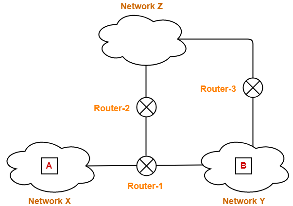


Consider Router-1 receives a datagram from host A having-

  • Header length = 20 bytes
  • Payload length = 500 bytes
  • Total length = 520 bytes
  • DF bit set to 0


Consider Router-1 divides the datagram into 3 fragments as discussed in Example-01.


Then,

  • First fragment contains the data = 176 bytes
  • Second fragment contains the data = 176 byes
  • Third fragment contains the data = 148 bytes


Now, consider-

  • First and third fragment reaches the destination directly.
  • However,  second fragment takes its way through network Z and reach the destination through Router-3.


Journey Of Second Fragment-


Now, let us discuss the journey of fragment-2 and how it finally reaches the destination.


Router-2 receives a datagram (second fragment of original datagram) where-

  • Header length = 20 bytes
  • Payload length = 176 bytes
  • Total length = 196 bytes
  • DF bit set to 0


Now, Router-2 works in the following steps-


Step-01:


Router-2 examines the datagram and finds-

  • Size of the datagram = 196 bytes
  • Destination is network Z having MTU = 110 bytes
  • DF bit is set to 0


Router-2 concludes-

  • Size of the datagram is greater than MTU.
  • So, it will have to divide the datagram into fragments.
  • DF bit is set to 0.
  • So, it is allowed to create fragments of the datagram.


Step-02:


Router-2 decides the amount of data that it should transmit in each fragment.


Router-2 knows-

  • MTU of the destination network = 110 bytes.
  • So, maximum total length of any fragment can be only 110 bytes.
  • Out of 110 bytes, 20 bytes will be taken by the header.
  • So, maximum amount of data that can be sent in any fragment = 90 bytes.


Following the rule,

  • Router-2 decides to send maximum 88 bytes of data in one fragment.
  • This is because it is the greatest value that is a multiple of 8 and less than MTU.


Step-03:


Router-2 creates two fragments of the received datagram where-

  • First fragment contains the data = 88 bytes
  • Second fragment contains the data = 88 byes
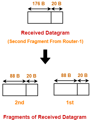


The information contained in the IP header of each fragment is-


Header Information Of 1st Fragment-


  • Header length field value = 20 / 4 = 5
  • Total length field value = 88 + 20 = 108
  • MF bit = 1
  • Fragment offset field value = 176 / 8 = 22
  • Header checksum is recalculated.
  • Identification number is same as that of original datagram.


NOTE-


  • This fragment is NOT the first fragment of the original datagram.
  • It is the first fragment of the datagram received by Router-2.
  • The datagram received by Router-2 is the second fragment of the original datagram.
  • This datagram will serve as the second fragment of the original datagram.
  • Therefore, fragment offset field is set according to the first fragment of the original datagram.


Header Information Of 2nd Fragment-


  • Header length field value = 20 / 4 = 5
  • Total length field value = 88 + 20 = 108
  • MF bit = 1
  • Fragment offset field value = (176 + 88) / 8 = 33
  • Header checksum is recalculated.
  • Identification number is same as that of original datagram.


NOTE-


  • This fragment is NOT the last fragment of the original datagram.
  • It is the last fragment of the datagram received by Router-2.
  • The datagram received by Router-2 is the second fragment of the original datagram.
  • This datagram will serve as the third fragment of the original datagram.
  • There is another fragment of the original datagram that follows it.
  • That is why, here MF bit is not set to 0.


Router-2 transmits both the fragments which reaches the destination through Router-3.

Router-3 performs no fragmentation.


Step-04:


At destination side,

  • Receiver receives 4 fragments of the datagram.
  • Reassembly algorithm is applied to combine all the fragments to obtain the original datagram.


Reassembly Algorithm-


Receiver applies the following steps for reassembly of all the fragments-

  1. It identifies whether datagram is fragmented or not using MF bit and Fragment offset field.
  2. It identifies all the fragments belonging to the same datagram using identification field.
  3. It identifies the first fragment. Fragment with offset field value = 0 is the first fragment.
  4. It identifies the subsequent fragments using total length, header length and fragment offset.
  5. It repeats step-04 until MF bit = 0.


Fragment Offset field value for the next subsequent fragment

= ( Payload length of the current fragment / 8 ) + Offset field value of the current fragment

= ( Total length – Header length / 8 ) + Offset field value of the current fragment


Fragmentation Overhead-


  • Fragmentation of datagram increases the overhead.
  • This is because after fragmentation, IP header has to be attached with each fragment.


Total Overhead

= (Total number of fragmented datagrams – 1) x size of IP header


Efficiency = Useful bytes transferred / Total bytes transferred

OR

Efficiency = Data without header / Data with header


Bandwidth Utilization or Throughput = Efficiency x Bandwidth


Important Notes-


Note-01:


  • Source side does not require fragmentation due to wise segmentation by transport layer.
  • The transport layer looks at the datagram data limit and frame data limit.
  • Then, it performs segmentation in such a way that the resulting data can easily fit in a frame.
  • Thus, there is no need of fragmentation at the source side.


Note-02:


  • Datagrams from the same source to the same destination may take different routes in the network.


Note-03:


  • Fragment offset field value is set to 0 for the first fragmented datagram.
  • MF bit is set to 1 for all the fragmented datagrams except the last one.


Note-04:


  • Unique combinations of MF bit value and fragment offset value.


MF bit Offset value Represents
1 0 1st Fragment
1 !=0 Intermediate Fragment
0 !=0 Last Fragment
0 0 No Fragmentation


Note-05:


  • Identification number for all the fragments is same as that of the original datagram.
  • This is to identify all the fragments of the same datagram while re-assembling them.


Note-06:


  • Consider datagram goes through a path where different intermediaries having different bandwidths.
  • Then, while calculating the throughput, consider the minimum bandwidth since it act as a bottleneck.


Note-07:


  • Fragmentation is done by intermediary devices such as routers.
  • The reassembly of fragmented datagrams is done only after reaching the destination.


Note-08:


Reassembly is not done at the routers because-

  • All the fragments may not meet at the router.
  • Fragmented datagrams may reach the destination through independent paths.
  • There may be a need for further fragmentation.


Note-09:


If a fragment (say parent) is re fragmented into multiple datagrams then-

  1. The fragment offset value for the first re-fragment is always same as its parent.
  2. The MF bit bit value for the last re-fragment is always same as its parent.


To gain better understanding about IP Fragmentation,

Watch this Video Lecture


Next Article- Practice Problems On IP Fragmentation


Get more notes and other study material of Computer Networks.

Watch video lectures by visiting our YouTube channel LearnVidFun.
IPv4 | IPv4 Header | IPv4 Header Format

Internet Protocol Version 4-


  • IPv4 short for Internet Protocol Version 4 is the fourth version of the Internet Protocol (IP).
  • IP is responsible to deliver data packets from the source host to the destination host.
  • This delivery is solely based on the IP Addresses in the packet headers.
  • IPv4 is the first major version of IP.
  • IPv4 is a connectionless protocol for use on packet-switched networks.


In this article, we will discuss about IPv4 Header.


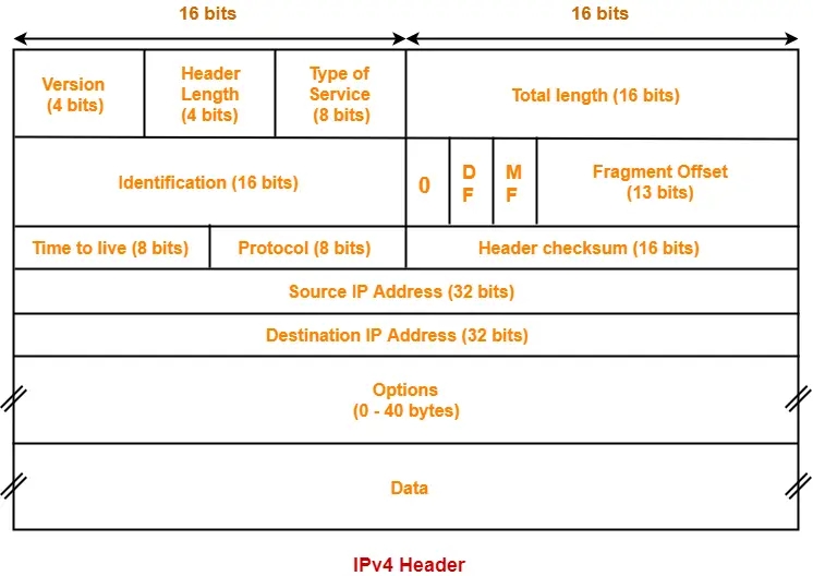
IPv4 Header-


The following diagram represents the IPv4 header-


Let us discuss each field of IPv4 header one by one.


1. Version-


  • Version is a 4 bit field that indicates the IP version used.
  • The most popularly used IP versions are version-4 (IPv4) and version-6 (IPv6).
  • Only IPv4 uses the above header.
  • So, this field always contains the decimal value 4.


NOTES

It is important to note-

  • Datagrams belonging to different versions have different structures.
  • So, they are parsed differently.
  • IPv4 datagrams are parsed by version-4 parsers.
  • IPv6 datagrams are parsed by version-6 parsers.


2. Header Length-


  • Header length is a 4 bit field that contains the length of the IP header.
  • It helps in knowing from where the actual data begins.


Minimum And Maximum Header Length-


The length of IP header always lies in the range-

[20 bytes , 60 bytes]


  • The initial 5 rows of the IP header are always used.
  • So, minimum length of IP header = 5 x 4 bytes = 20 bytes.
  • The size of the 6th row representing the Options field vary.
  • The size of Options field can go up to 40 bytes.
  • So, maximum length of IP header = 20 bytes + 40 bytes = 60 bytes.


Concept of Scaling Factor-


  • Header length is a 4 bit field.
  • So, the range of decimal values that can be represented is [0, 15].
  • But the range of header length is [20, 60].
  • So, to represent the header length, we use a scaling factor of 4.


In general,


Header length = Header length field value x 4 bytes


Examples-


  • If header length field contains decimal value 5 (represented as 0101), then-

Header length = 5 x 4 = 20 bytes

  • If header length field contains decimal value 10 (represented as 1010), then-

Header length = 10 x 4 = 40 bytes

  • If header length field contains decimal value 15 (represented as 1111), then-

Header length = 15 x 4 = 60 bytes


NOTES

It is important to note-

  • Header length and Header length field value are two different things.
  • The range of header length field value is always [5, 15].
  • The range of header length is always [20, 60].


While solving questions-

  • If the given value lies in the range [5, 15] then it must be the header length field value.
  • This is because the range of header length is always [20, 60].


3. Type Of Service-


  • Type of service is a 8 bit field that is used for Quality of Service (QoS).
  • The datagram is marked for giving a certain treatment using this field.


4. Total Length-


  • Total length is a 16 bit field that contains the total length of the datagram (in bytes).


Total length = Header length + Payload length


  • Minimum total length of datagram = 20 bytes (20 bytes header + 0 bytes data)
  • Maximum total length of datagram = Maximum value of 16 bit word = 65535 bytes


5. Identification-


  • Identification is a 16 bit field.
  • It is used for the identification of the fragments of an original IP datagram.


When an IP datagram is fragmented,

  • Each fragmented datagram is assigned the same identification number.
  • This number is useful during the re assembly of fragmented datagrams.
  • It helps to identify to which IP datagram, the fragmented datagram belongs to.


6. DF Bit-


  • DF bit stands for Do Not Fragment bit.
  • Its value may be 0 or 1.


When DF bit is set to 0,

  • It grants the permission to the intermediate devices to fragment the datagram if required.


When DF bit is set to 1,

  • It indicates the intermediate devices not to fragment the IP datagram at any cost.
  • If network requires the datagram to be fragmented to travel further but settings does not allow its fragmentation, then it is discarded.
  • An error message is sent to the sender saying that the datagram has been discarded due to its settings.


7. MF Bit-


  • MF bit stands for More Fragments bit.
  • Its value may be 0 or 1.


When MF bit is set to 0,

  • It indicates to the receiver that the current datagram is either the last fragment in the set or that it is the only fragment.


When MF bit is set to 1,

  • It indicates to the receiver that the current datagram is a fragment of some larger datagram.
  • More fragments are following.
  • MF bit is set to 1 on all the fragments except the last one.


8. Fragment Offset-


  • Fragment Offset is a 13 bit field.
  • It indicates the position of a fragmented datagram in the original unfragmented IP datagram.
  • The first fragmented datagram has a fragment offset of zero.


Fragment offset for a given fragmented datagram

= Number of data bytes ahead of it in the original unfragmented datagram


Concept Of Scaling Factor-


  • We use a scaling factor of 8 for the fragment offset.
  • Fragment offset field value = Fragment Offset / 8


Need Of Scaling Factor For Fragment Offset


  • In IPv4 header, the total length field comprises of 16 bits.
  • Total length = Header length + Payload length.
  • Minimum header length = 20 bytes.
  • So, maximum amount of data that can be sent in the payload field = 216 – 20 bytes.
  • In worst case, a datagram containing 216 – 20 bytes of data might be fragmented in such a way that the last fragmented datagram contains only 1 byte of data.
  • Then, fragment offset for the last fragmented datagram will be (216 – 20) – 1 = 216 -21 ≅ 216

(if no scaling factor is used)

  • Now, this fragment offset value of 216 can not be represented.
  • This is because the fragment offset field consists of only 13 bits.
  • Using 13 bits, a maximum number of 213 can be represented.
  • So, to represent 216 we use the concept of scaling factor.
  • Scaling factor = 216 / 213 = 23 = 8.


9. Time To Live-


  • Time to live (TTL) is a 8 bit field.
  • It indicates the maximum number of hops a datagram can take to reach the destination.
  • The main purpose of TTL is to prevent the IP datagrams from looping around forever in a routing loop.


The value of TTL is decremented by 1 when-

  • Datagram takes a hop to any intermediate device having network layer.
  • Datagram takes a hop to the destination.


If the value of TTL becomes zero before reaching the destination, then datagram is discarded.


NOTES

It is important to note-

  • Both intermediate devices having network layer and destination decrements the TTL value by 1.
  • If the value of TTL is found to be zero at any intermediate device, then the datagram is discarded.
  • So, at any intermediate device, the value of TTL must be greater than zero to proceed further.
  • If the value of TTL becomes zero at the destination, then the datagram is accepted.
  • So, at the destination, the value of TTL may be greater than or equal to zero.


10. Protocol-


  • Protocol is a 8 bit field.
  • It tells the network layer at the destination host to which protocol the IP datagram belongs to.
  • In other words, it tells the next level protocol to the network layer at the destination side.
  • Protocol number of ICMP is 1, IGMP is 2, TCP is 6 and UDP is 17.


Why Protocol Number Is A Part Of IP Header?


Consider-

  • An IP datagram is sent by the sender to the receiver.
  • When datagram reaches at the router, it’s buffer is already full.


In such a case,

  • Router does not discard the datagram directly.
  • Before discarding, router checks the next level protocol number mentioned in its IP header.
  • If the datagram belongs to TCP, then it tries to make room for the datagram in its buffer.
  • It creates a room by eliminating one of the datagrams having lower priority.
  • This is because it knows that TCP is a reliable protocol and if it discards the datagram, then it will be sent again by the sender.
  • The order in which router eliminate the datagrams from its buffer is-

ICMP > IGMP > UDP > TCP


If protocol number would have been inside the datagram, then-

  • Router could not look into it.
  • This is because router has only three layers- physical layer, data link layer and network layer.


That is why, protocol number is made a part of IP header.


11. Header Checksum-


  • Header checksum is a 16 bit field.
  • It contains the checksum value of the entire header.
  • The checksum value is used for error checking of the header.


At each hop,

  • The header checksum is compared with the value contained in this field.
  • If header checksum is found to be mismatched, then the datagram is discarded.
  • Router updates the checksum field whenever it modifies the datagram header.


The fields that may be modified are-

  1. TTL
  2. Options
  3. Datagram Length
  4. Header Length
  5. Fragment Offset


NOTE

It is important to note-

  • Computation of header checksum includes IP header only.
  • Errors in the data field are handled by the encapsulated protocol.


Also Read- Checksum


12. Source IP Address-


  • Source IP Address is a 32 bit field.
  • It contains the logical address of the sender of the datagram.


13. Destination IP Address-


  • Destination IP Address is a 32 bit field.
  • It contains the logical address of the receiver of the datagram.


14. Options-


  • Options is a field whose size vary from 0 bytes to 40 bytes.
  • This field is used for several purposes such as-
  1. Record route
  2. Source routing
  3. Padding


1. Record Route-


  • A record route option is used to record the IP Address of the routers through which the datagram passes on its way.
  • When record route option is set in the options field, IP Address of the router gets recorded in the Options field.


NOTE


The maximum number of IPv4 router addresses that can be recorded in the Record Route option field of an IPv4 header is 9.


Explanation-


  • In IPv4, size of IP Addresses = 32 bits = 4 bytes.
  • Maximum size of Options field = 40 bytes.
  • So, it seems maximum number of IP Addresses that can be recorded = 40 / 4 = 10.
  • But some space is required to indicate the type of option being used.
  • Also, some space is to be left between the IP Addresses.
  • So, the space of 4 bytes is left for this purpose.
  • Therefore, the maximum number of IP addresses that can be recorded = 9.


2. Source Routing-


  • A source routing option is used to specify the route that the datagram must take to reach the destination.
  • This option is generally used to check whether a certain path is working fine or not.
  • Source routing may be loose or strict.


3. Padding-


  • Addition of dummy data to fill up unused space in the transmission unit and make it conform to the standard size is called as padding.
  • Options field is used for padding.


Example-


  • When header length is not a multiple of 4, extra zeroes are padded in the Options field.
  • By doing so, header length becomes a multiple of 4.
  • If header length = 30 bytes, 2 bytes of dummy data is added to the header.
  • This makes header length = 32 bytes.
  • Then, the value 32 / 4 = 8 is put in the header length field.
  • In worst case, 3 bytes of dummy data might have to be padded to make the header length a multiple of 4.


Also Read- TCP Header | UDP Header


To gain better understanding about IPv4 Header,

Watch this Video Lecture


Next Article- IP Fragmentation | Examples


Get more notes and other study material of Computer Networks.

Watch video lectures by visiting our YouTube channel LearnVidFun.
Time Out Timer | Karn Algorithm | Jacobson Algorithm

TCP Timers-


Before you go through this article, make sure that you have gone through the previous article on TCP Timers.


We have discussed-

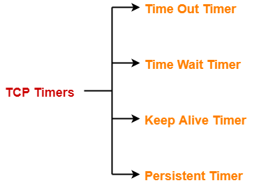
  • TCP Timers are used to avoid excessive delays during communication.
  • Several timers used in a TCP implementation are-


  1. Time Out Timer
  2. Time Wait Timer
  3. Keep Alive Timer
  4. Persistent Timer


In this article, we will discuss about Time Out Timer and its Computation.


Time Out Timer-


TCP uses a time out timer for retransmission of lost segments.


  • Sender starts a time out timer after transmitting a TCP segment to the receiver.
  • If sender receives an ACK before the timer goes off, it stops the timer.
  • If sender does not receives any ACK and the timer goes off, then TCP Retransmission occurs.
  • Sender retransmits the same segment and resets the timer.
  • The value of time out timer is dynamic and changes with the amount of traffic in the network.


Network Traffic And Time Out Timer-


Consider-

  • Receiver has sent the ACK to the sender.
  • The ACK is on its way through the network.


Now, following two cases are possible-


Case-01: High traffic-


If there is high traffic in the network-

  • The time taken by the ACK to reach the sender will be more.
  • So, as per the high traffic, the value of time out timer should be kept large.


If the value is kept small, then-

  • Timer will time out soon.
  • It causes the sender to assume that the segment is lost before reaching the receiver.
  • However, in actual the ACK is delayed due to high traffic.
  • Sender keeps retransmitting the same segment.
  • This overburdens the network and might lead to congestion.


Case-02: Low traffic-


If there is low traffic in the network-

  • The time taken by the ACK to reach the sender will be less.
  • So, as per the low traffic, the value of time out timer should be kept small.


If the value is kept large,

  • Timer will not time out soon.
  • Sender keeps waiting for the ACK even when it is actually lost.
  • This causes excessive delay.


Conclusion-


The value of time out timer should be such that-

  • It decreases when there is low traffic traffic in the network.
  • It increases when there is high traffic in the network.


Algorithms For Computing Time Out Timer Value-


The algorithms used for computing the value of time out timer dynamically are-

  1. Basic Algorithm
  2. Jacobson’s Algorithm
  3. Karn’s modification


Rules


All the above algorithms work on the following rules-


Rule-01:


The value of time out timer for the next segment is increased when-

  • Actual round trip time for the previous segment is found to be increased indicating there is high traffic in the network.


Rule-02:


The value of time out timer for the next segment is decreased when-

  • Actual round trip time for the previous segment is found to be decreased indicating there is low traffic in the network.


Now, let us see all the algorithms one by one.


Basic Algorithm-


The steps followed under Basic Algorithm are-


Step-01: Sending 1st Segment-


While sending the 1st segment,

  • Sender assumes any random value of initial RTT say IRTT1.
  • So after sending the 1st segment, sender expects its ACK to arrive in time IRTT1.
  • Sender sets time out timer value (TOT) for the 1st segment to be-


TOT1 = 2 X IRTT1


  • Suppose ACK for the 1st segment arrives in time ARTT1.
  • Here, ARTT1 = Actual Round Trip Time for the 1st segment.


Step-02: Sending 2nd Segment-


While sending the 2nd segment,

  • Sender computes the value of initial RTT for the 2nd segment using the relation-


IRTTn+1 = α IRTTn + (1 – α)ARTTn


Here, α is called smoothing factor where 0 <= α <= 1

(Its value will be given in questions)


Now,

  • Substituting n=1, sender gets IRTT2 = α IRTT1 + (1 – α)ARTT1.
  • So after sending the 2nd segment, sender expects its ACK to arrive in time IRTT2.
  • Sender sets time out timer value (TOT) for the 2nd segment to be-


TOT2 = 2 X IRTT2


  • Suppose ACK for the 2nd segment arrives in time ARTT2.
  • Here, ARTT2 = Actual Round Trip Time for the 2nd segment.


In the similar manner, algorithm computes the time out timer value for all the further segments.


Advantages-


The advantages of Basic Algorithm are-

  • Time out timer value is flexible to dynamic round trip time.
  • It takes into consideration all the previously sent segments to derive the initial RTT for the current segment.


Disadvantage-


The disadvantage of Basic Algorithm is-

  • It always considers Time out timer value = 2 x Initial round trip time.
  • There is no logic behind using the number 2.


2. Jacobson’s Algorithm-


  • Jacobson’s Algorithm is a modified version of the basic algorithm.
  • It gives better performance than Basic Algorithm.


The steps involved in Jacobson’s Algorithm are-


Step-01: Sending 1st Segment-


While sending the 1st segment,

  • Sender assumes any random value of initial RTT say IRTT1.
  • So after sending the 1st segment, sender expects its ACK to arrive in time IRTT1.
  • Sender assumes any random value of initial deviation say ID1.
  • So after sending the 1st segment, sender expects there will be a deviation of ID1 time from IRTT1.
  • Sender sets time out timer value (TOT) for the 1st segment to be-


TOT1 = 4 x ID1 + IRTT1


  • Suppose ACK for the 1st segment arrives in time ARTT1.
  • Here, ARTT1 = Actual Round Trip Time for the 1st segment.
  • Then, Actual deviation from IRTT1 is given by-

AD1 = | IRTT1 – ARTT1 |


Step-02: Sending 2nd Segment-


While sending the 2nd segment,

  • Sender computes the value of initial RTT for the 2nd segment using the relation-


IRTTn+1 = α IRTTn + (1 – α)ARTTn


Here, α is called smoothing factor where 0 <= α <= 1

(Its value will be given in questions)

  • Sender computes the value of initial deviation for the 2nd segment using the relation-


IDn+1 = α IDn + (1 – α)ADn


Here, α is called smoothing factor where 0 <= α <= 1

(Its value will be given in questions)

  • Substituting n=1, sender gets-

IRTT2 = α IRTT1 + (1 – α)ARTT1

ID2 = α ID1 + (1 – α)AD1


  • So after sending the 2nd segment, sender expects its ACK to arrive in time IRTT2 with deviation of IDtime.
  • Sender sets time out timer value (TOT) for the 2nd segment to be-


TOT2 = 4 x ID2 + IRTT2


  • Suppose ACK for the 2nd segment arrives in time ARTT2.
  • Here, ARTT2 = Actual Round Trip Time for the 2nd segment.
  • Then, Actual deviation from IRTT2 is given by-

AD2 = | IRTT2 – ARTT2 |


In the similar manner, algorithm computes the time out timer value for all the further segments.


Problems with Basic Algorithm and Jacobson’s Algorithm-


To calculate initial round trip time, both the algorithms depend on the actual round trip time of the previous segment through the relation-


IRTTn+1 = α IRTTn + (1 – α)ARTTn


Now,

  • Consider ACK of some segment arrives to the sender after its initial time out timer goes off.
  • Then, sender will have to re transmit the segment.
  • Now for the segment being re transmitted, what should be the initial time out timer value is the concern.
  • This is because the ACK is delayed and will arrive after time out.
  • So, ARTT is not available.


This problem is resolved by Karn’s modification.


3. Karn’s Modification-


Karn’s modification states-

  • Whenever a segment has to be re transmitted, do not apply either of Basic or Jacobson’s algorithm since actual RTT is not available.
  • Instead, double the time out timer (TOT) whenever the timer times out and make a retransmission.


NOTE

In the above discussion,

Initial time out timer value may also be called as the estimated time out timer value for the segment being sent.


PRACTICE PROBLEMS BASED ON CALCULATING TIME OUT TIMER VALUE-


Problem-01:


In TCP, the initial RTT is 10 msec. The acknowledgements for the first three segments are received in time 15 msec, 20 msec and 10 msec.

Find the time out timer value for the first four segments using basic algorithm. Use α = 0.5.


Solution-


For 1st Segment-


Initial round trip time (IRTT1) = 10 msec


So, Time out timer value (TOT1)

= 2 x IRTT1

= 2 x 10

= 20 msec


Now,

  • ACK for the 1st segment is received after 15 msec.
  • So, Actual round trip time (ARTT1) = 15 msec.


For 2nd Segment-


Initial round trip time (IRTT2)

= α x IRTT1 + (1-α) x ARTT1

= 0.5 x 10 + (1-0.5) x 15

= 5 + 7.5

= 12.5 msec


So, Time out timer value (TOT2)

= 2 x IRTT2

= 2 x 12.5

= 25 msec


Now,

  • ACK for the 2nd segment is received after 20 msec.
  • So, Actual round trip time (ARTT2) = 20 msec.


For 3rd Segment-


Initial round trip time (IRTT3)

= α x IRTT2 + (1-α) x ARTT2

= 0.5 x 12.5 + (1-0.5) x 20

= 6.25 + 10

= 16.25 msec


So, Time out timer value (TOT3)

= 2 x IRTT3

= 2 x 16.25

= 32.5 msec


Now,

  • ACK for the 3rd segment is received after 10 msec.
  • So, Actual round trip time (ARTT3) = 10 msec.


For 4th Segment-


Initial round trip time (IRTT4)

= α x IRTT3 + (1-α) x ARTT3

= 0.5 x 16.25 + (1-0.5) x 10

= 8.125 + 5

= 13.125 msec


So, Time out timer value (TOT4)

= 2 x IRTT4

= 2 x 13.125

= 26.25 msec


Problem-02:


In TCP, the initial RTT is 10 msec and the initial deviation is 5 msec. The acknowledgements for the first three segments are received in time 20 msec, 30 msec and 10 msec.

Find the time out timer value for the first four segments using Jacobson’s Algorithm. Use α = 0.5.


Solution-


For 1st Segment-


  • Initial round trip time (IRTT1) = 10 msec
  • Initial deviation (ID1) = 5 msec


So,

Time out timer value (TOT1)

= 4 x ID1 + IRTT1

= 4 x 5 + 10

= 30 msec


Now, ACK for the 1st segment is received after 20 msec. So,

  • Actual round trip time (ARTT1) = 20 msec
  • Actual deviation (AD1) = | IRTT1 – ARTT1 | = | 10 – 20 | = 10 msec


For 2nd Segment-


Initial round trip time (IRTT2)

= α x IRTT1 + (1-α) x ARTT1

= 0.5 x 10 + (1-0.5) x 20

= 5 + 10

= 15 msec


Initial deviation (ID2)

= α x ID1 + (1-α) x AD1

= 0.5 x 5 + (1-0.5) x 10

= 2.5 + 5

= 7.5 msec


So, Time out timer value (TOT2)

= 4 x ID2 + IRTT2

= 4 x 7.5 + 15

= 45 msec


Now, ACK for the 2nd segment is received after 30 msec. So,

  • Actual round trip time (ARTT2) = 30 msec
  • Actual deviation (AD2) = | IRTT2 – ARTT2 | = | 15 – 30 | = 15 msec


For 3rd Segment-


Initial round trip time (IRTT3)

= α x IRTT2 + (1-α) x ARTT2

= 0.5 x 15 + (1-0.5) x 30

= 7.5 + 15

= 22.5 msec


Initial deviation (ID3)

= α x ID2 + (1-α) x AD2

= 0.5 x 7.5 + (1-0.5) x 15

= 3.75 + 7.5

= 11.25 msec


So, Time out timer value (TOT3)

= 4 x ID3 + IRTT3

= 4 x 11.25 + 22.5

= 67.5 msec


Now, ACK for the 3rd segment is received after 10 msec. So,

  • Actual round trip time (ARTT3) = 10 msec
  • Actual deviation (AD3) = | IRTT3 – ARTT3 | = | 22.5 – 10 | = 12.5 msec


For 4th Segment-


Initial round trip time (IRTT4)

= α x IRTT3 + (1-α) x ARTT3

= 0.5 x 22.5 + (1-0.5) x 10

= 11.25 + 5

= 16.25 msec


Initial deviation (ID3)

= α x ID3 + (1-α) x AD3

= 0.5 x 11.25 + (1-0.5) x 12.5

= 5.625 + 6.25

= 11.875 msec


So, Time out timer value (TOT4)

= 4 x ID4 + IRTT4

= 4 x 11.875 + 16.25

= 63.75 msec


Next Article- Silly Window Syndrome


Get more notes and other study material of Computer Networks.

Watch video lectures by visiting our YouTube channel LearnVidFun.

Silly Window Syndrome | Nagle’s Algorithm

Silly Window Syndrome-


  • Silly Window Syndrome is a problem that arises due to the poor implementation of TCP.
  • It degrades the TCP performance and makes the data transmission extremely inefficient.


Why This Name?


The problem is called so because-

  • It causes the sender window size to shrink to a silly value.
  • The window size shrinks to such an extent where the data being transmitted is smaller than TCP Header.


Causes-


The problem arises due to following causes-


  1. Sender transmitting data in small segments repeatedly
  2. Receiver accepting only few bytes at a time repeatedly


Cause-01: Sender Transmitting Data In Small Segments Repeatedly-


  • Consider application generates one byte of data to send at a time.
  • The poor implementation of TCP causes the sender to send each byte of data in an individual TCP segment.


This problem is solved using Nagle’s Algorithm.


Nagle’s Algorithm-


Nagle’s Algorithm tries to solve the problem

caused by the sender delivering 1 data byte at a time.


Nagle’s algorithm suggests-

  • Sender should send only the first byte on receiving one byte data from the application.
  • Sender should buffer all the rest bytes until the outstanding byte gets acknowledged.
  • In other words, sender should wait for 1 RTT.
  • After receiving the acknowledgement, sender should send the buffered data in one TCP segment.
  • Then, sender should buffer the data again until the previously sent data gets acknowledged.


Cause-02: Receiver Accepting Only Few Bytes Repeatedly-


  • Consider the receiver continues to be unable to process all the incoming data.
  • In such a case, its window size becomes smaller and smaller.
  • A stage arrives when it repeatedly sends the window size of 1 byte to the sender.


This problem is solved using Clark’s Solution.


Clark’s Solution-


Clark’s Solution tries to solve the problem

caused by the receiver sucking up one data byte at a time.


Clark’s solution suggests-

  • Receiver should not send a window update for 1 byte.
  • Receiver should wait until it has a decent amount of space available.
  • Receiver should then advertise that window size to the sender.


Specifically, the receiver should not send a window update-

  • Until it can handle the MSS it advertised during Three Way Handshake
  • Or until its buffer is half empty, whichever is smaller.


Important Notes-


Note-01:


Nagle’s algorithm is turned off for the applications that require data to be sent immediately.


This is because-

  • Nagle’s algorithm sends only one segment per round trip time.
  • This impacts the latency by introducing a delay.


Note-02:


Nagle’s algorithm and Clark’s solution are complementary.


  • Both Nagle’s solution and Clark’s solution can work together.
  • The ultimate goal is sender should not send the small segments and receiver should not ask for them.


PRACTICE PROBLEM BASED ON NAGLE’S ALGORITHM-


Problem-


A fast typist can do 100 words a minute and each word has an average of 6 characters. Demonstrate Nagle’s algorithm by showing the sequence of TCP segment exchanges between a client with input from our fast typist and a server. Indicate how many characters are contained in each segment sent from the client.


Consider the following two cases-

  1. The client and server are in the same LAN and the RTT is 20 ms.
  2. The client and server are connected across a WAN and the RTT is 100 ms.


Solution-


Nagle’s algorithm suggests-

  • Sender should wait for 1 RTT before sending the data.
  • The amount of data received from the application layer in 1 RTT should be sent to the receiver.


Case-01:


Amount of data accumulated in 1 RTT

= (600 characters / 1 minute) x 20 msec

= (600 characters / 60 sec) x 20 msec

= (10 characters / 103 msec) x 20 msec

= 0.2 characters


From here, we observe-

  • Even if the sender waits for 1 RTT, not even a single character is produced.
  • So, sender will have to wait till it receives at least 1 character.
  • Then, sender sends it in one segment.


Thus, one character will be sent per segment.

Assuming the TCP header length is 20 bytes, 41 bytes of data will be sent in each segment.


Case-02:


Amount of data accumulated in 1 RTT

= (600 characters / 1 minute) x 100 msec

= (600 characters / 60 sec) x 100 msec

= (10 characters / 103 msec) x 100 msec

= 1 character


From here, we observe that one character is produced in 1 RTT.


Thus, one character will be sent per segment.

Assuming the TCP header length is 20 bytes, 41 bytes of data will be sent in each segment.


Next Article- User Datagram Protocol | UDP Header


Get more notes and other study material of Computer Networks.

Watch video lectures by visiting our YouTube channel LearnVidFun.

TCP Timers | Time Out Timer | Time Wait Timer

TCP Timers-


Timers used by TCP to avoid excessive delays during communication are called as TCP Timers.


The 4 important timers used by a TCP implementation are-


  1. Time Out Timer
  2. Time Wait Timer
  3. Keep Alive Timer
  4. Persistent Timer


Time Out Timer-


TCP uses a time out timer for retransmission of lost segments.


  • Sender starts a time out timer after transmitting a TCP segment to the receiver.
  • If sender receives an acknowledgement before the timer goes off, it stops the timer.
  • If sender does not receives any acknowledgement and the timer goes off, then TCP Retransmission occurs.
  • Sender retransmits the same segment and resets the timer.
  • The value of time out timer is dynamic and changes with the amount of traffic in the network.
  • Time out timer is also called as Retransmission Timer.


Time Wait Timer-


TCP uses a time wait timer during connection termination.


  • Sender starts the time wait timer after sending the ACK for the second FIN segment.
  • It allows to resend the final acknowledgement if it gets lost.
  • It prevents the just closed port from reopening again quickly to some other application.
  • It ensures that all the segments heading towards the just closed port are discarded.
  • The value of time wait timer is usually set to twice the lifetime of a TCP segment.


Also Read- TCP Connection Termination


Keep Alive Timer-


TCP uses a keep alive timer to prevent long idle TCP connections.


  • Each time server hears from the client, it resets the keep alive timer to 2 hours.
  • If server does not hear from the client for 2 hours, it sends 10 probe segments to the client.
  • These probe segments are sent at a gap of 75 seconds.
  • If server receives no response after sending 10 probe segments, it assumes that the client is down.
  • Then, server terminates the connection automatically.


Persistent Timer-


  • TCP uses a persistent timer to deal with a zero-widow-size deadlock situation.
  • It keeps the window size information flowing even if the other end closes its receiver window.


Explanation


Consider the following situation-

  • Sender receives an acknowledgment from the receiver with zero window size.
  • This indicates the sender to wait.
  • Later, receiver updates the window size and and sends the segment with the update to the sender.
  • This segment gets lost.
  • Now, both sender and receiver keeps waiting for each other to do something.

To deal with such a situation, TCP uses a persistent timer.


Also Read- Silly Window Syndrome


  • Sender starts the persistent timer on receiving an ACK from the receiver with a zero window size.
  • When persistent timer goes off, sender sends a special segment to the receiver.
  • This special segment is called as probe segment and contains only 1 byte of new data.
  • Response sent by the receiver to the probe segment gives the updated window size.
  • If the updated window size is non-zero, it means data can be sent now.
  • If the updated window size is still zero, the persistent timer is set again and the cycle repeats.


Next Article- Time Out Timer | Computation Algorithms


Get more notes and other study material of Computer Networks.

Watch video lectures by visiting our YouTube channel LearnVidFun.