IP Fragmentation-
- IP Fragmentation is a process of dividing the datagram into fragments during its transmission.
- It is done by intermediary devices such as routers at the destination host at network layer.

Need-
- Each network has its maximum transmission unit (MTU).
- It dictates the maximum size of the packet that can be transmitted through it.
- Data packets of size greater than MTU can not be transmitted through the network.
- So, datagrams are divided into fragments of size less than or equal to MTU.
Datagram Fragmentation-
When router receives a datagram to transmit further, it examines the following-
- Size of the datagram
- MTU of the destination network
- DF bit value in the IP header
Then, following cases are possible-
Case-01:
- Size of the datagram is found to be smaller than or equal to MTU.
- In this case, router transmits the datagram without any fragmentation.
Case-02:
- Size of the datagram is found to be greater than MTU and DF bit set to 1.
- In this case, router discards the datagram.
Case-03:
- Size of the datagram is found to be greater than MTU and DF bit set to 0.
- In this case, router divides the datagram into fragments of size less than or equal to MTU.
- Router attaches an IP header with each fragment making the following changes in it.
- Then, router transmits all the fragments of the datagram.
Changes Made By Router-
Router makes the following changes in IP header of each fragment-
- It changes the value of total length field to the size of fragment.
- It sets the MF bit to 1 for all the fragments except the last one.
- For the last fragment, it sets the MF bit to 0.
- It sets the fragment offset field value.
- It recalculates the header checksum.
Also Read- IPv4 Header
IP Fragmentation Examples-
Now, lets us discuss some examples of IP fragmentation to understand how the fragmentation is actually carried out.
Example-01:
Consider-
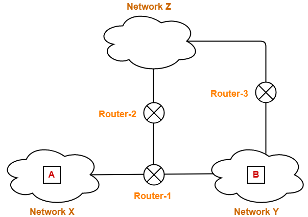
- There is a host A present in network X having MTU = 520 bytes.
- There is a host B present in network Y having MTU = 200 bytes.
- Host A wants to send a message to host B.

Consider router receives a datagram from host A having-
- Header length = 20 bytes
- Payload length = 500 bytes
- Total length = 520 bytes
- DF bit set to 0
Now, router works in the following steps-
Step-01:
Router examines the datagram and finds-
- Size of the datagram = 520 bytes
- Destination is network Y having MTU = 200 bytes
- DF bit is set to 0
Router concludes-
- Size of the datagram is greater than MTU.
- So, it will have to divide the datagram into fragments.
- DF bit is set to 0.
- So, it is allowed to create fragments of the datagram.
Step-02:
Router decides the amount of data that it should transmit in each fragment.
Router knows-
- MTU of the destination network = 200 bytes.
- So, maximum total length of any fragment can be only 200 bytes.
- Out of 200 bytes, 20 bytes will be taken by the header.
- So, maximum amount of data that can be sent in any fragment = 180 bytes.
Router uses the following rule to choose the amount of data that will be transmitted in one fragment-
RULE
The amount of data sent in one fragment is chosen such that-
NOTE
|
Following the above rule,
- Router decides to send maximum 176 bytes of data in one fragment.
- This is because it is the greatest value that is a multiple of 8 and less than MTU.
Step-03:
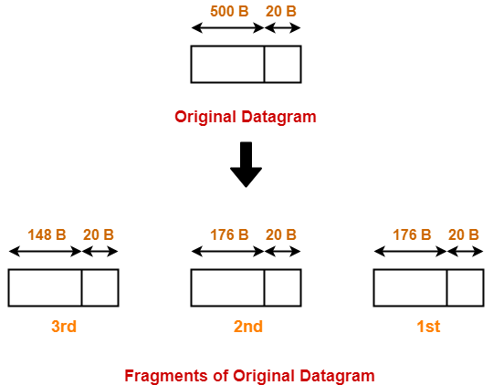
Router creates three fragments of the original datagram where-
- First fragment contains the data = 176 bytes
- Second fragment contains the data = 176 byes
- Third fragment contains the data = 148 bytes

The information contained in the IP header of each fragment is-
Header Information Of 1st Fragment-
- Header length field value = 20 / 4 = 5
- Total length field value = 176 + 20 = 196
- MF bit = 1
- Fragment offset field value = 0
- Header checksum is recalculated.
- Identification number is same as that of original datagram.
Header Information Of 2nd Fragment-
- Header length field value = 20 / 4 = 5
- Total length field value = 176 + 20 = 196
- MF bit = 1
- Fragment offset field value = 176 / 8 = 22
- Header checksum is recalculated.
- Identification number is same as that of original datagram.
Header Information Of 3rd Fragment-
- Header length field value = 20 / 4 = 5
- Total length field value = 148 + 20 = 168
- MF bit = 0
- Fragment offset field value = (176 + 176) / 8 = 44
- Header checksum is recalculated.
- Identification number is same as that of original datagram.
Router transmits all the fragments.
Step-04:
At destination side,
- Receiver receives 3 fragments of the datagram.
- Reassembly algorithm is applied to combine all the fragments to obtain the original datagram.
Example-02:
Consider-
- There is a host A present in network X having MTU = 520 bytes.
- There is a host B present in network Y having MTU = 200 bytes.
- There exists a network Z having MTU = 110 bytes.
- Host A wants to send a message to host B.

Consider Router-1 receives a datagram from host A having-
- Header length = 20 bytes
- Payload length = 500 bytes
- Total length = 520 bytes
- DF bit set to 0
Consider Router-1 divides the datagram into 3 fragments as discussed in Example-01.
Then,
- First fragment contains the data = 176 bytes
- Second fragment contains the data = 176 byes
- Third fragment contains the data = 148 bytes
Now, consider-
- First and third fragment reaches the destination directly.
- However, second fragment takes its way through network Z and reach the destination through Router-3.
Journey Of Second Fragment-
Now, let us discuss the journey of fragment-2 and how it finally reaches the destination.
Router-2 receives a datagram (second fragment of original datagram) where-
- Header length = 20 bytes
- Payload length = 176 bytes
- Total length = 196 bytes
- DF bit set to 0
Now, Router-2 works in the following steps-
Step-01:
Router-2 examines the datagram and finds-
- Size of the datagram = 196 bytes
- Destination is network Z having MTU = 110 bytes
- DF bit is set to 0
Router-2 concludes-
- Size of the datagram is greater than MTU.
- So, it will have to divide the datagram into fragments.
- DF bit is set to 0.
- So, it is allowed to create fragments of the datagram.
Step-02:
Router-2 decides the amount of data that it should transmit in each fragment.
Router-2 knows-
- MTU of the destination network = 110 bytes.
- So, maximum total length of any fragment can be only 110 bytes.
- Out of 110 bytes, 20 bytes will be taken by the header.
- So, maximum amount of data that can be sent in any fragment = 90 bytes.
Following the rule,
- Router-2 decides to send maximum 88 bytes of data in one fragment.
- This is because it is the greatest value that is a multiple of 8 and less than MTU.
Step-03:
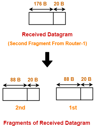
Router-2 creates two fragments of the received datagram where-
- First fragment contains the data = 88 bytes
- Second fragment contains the data = 88 byes

The information contained in the IP header of each fragment is-
Header Information Of 1st Fragment-
- Header length field value = 20 / 4 = 5
- Total length field value = 88 + 20 = 108
- MF bit = 1
- Fragment offset field value = 176 / 8 = 22
- Header checksum is recalculated.
- Identification number is same as that of original datagram.
NOTE-
- This fragment is NOT the first fragment of the original datagram.
- It is the first fragment of the datagram received by Router-2.
- The datagram received by Router-2 is the second fragment of the original datagram.
- This datagram will serve as the second fragment of the original datagram.
- Therefore, fragment offset field is set according to the first fragment of the original datagram.
Header Information Of 2nd Fragment-
- Header length field value = 20 / 4 = 5
- Total length field value = 88 + 20 = 108
- MF bit = 1
- Fragment offset field value = (176 + 88) / 8 = 33
- Header checksum is recalculated.
- Identification number is same as that of original datagram.
NOTE-
- This fragment is NOT the last fragment of the original datagram.
- It is the last fragment of the datagram received by Router-2.
- The datagram received by Router-2 is the second fragment of the original datagram.
- This datagram will serve as the third fragment of the original datagram.
- There is another fragment of the original datagram that follows it.
- That is why, here MF bit is not set to 0.
Router-2 transmits both the fragments which reaches the destination through Router-3.
Router-3 performs no fragmentation.
Step-04:
At destination side,
- Receiver receives 4 fragments of the datagram.
- Reassembly algorithm is applied to combine all the fragments to obtain the original datagram.

Reassembly Algorithm-
Receiver applies the following steps for reassembly of all the fragments-
- It identifies whether datagram is fragmented or not using MF bit and Fragment offset field.
- It identifies all the fragments belonging to the same datagram using identification field.
- It identifies the first fragment. Fragment with offset field value = 0 is the first fragment.
- It identifies the subsequent fragments using total length, header length and fragment offset.
- It repeats step-04 until MF bit = 0.
|
Fragment Offset field value for the next subsequent fragment = ( Payload length of the current fragment / 8 ) + Offset field value of the current fragment = ( Total length – Header length / 8 ) + Offset field value of the current fragment |
Fragmentation Overhead-
- Fragmentation of datagram increases the overhead.
- This is because after fragmentation, IP header has to be attached with each fragment.
| Total Overhead
= (Total number of fragmented datagrams – 1) x size of IP header |
|
Efficiency = Useful bytes transferred / Total bytes transferred OR Efficiency = Data without header / Data with header |
| Bandwidth Utilization or Throughput = Efficiency x Bandwidth |
Important Notes-
Note-01:
- Source side does not require fragmentation due to wise segmentation by transport layer.
- The transport layer looks at the datagram data limit and frame data limit.
- Then, it performs segmentation in such a way that the resulting data can easily fit in a frame.
- Thus, there is no need of fragmentation at the source side.
Note-02:
- Datagrams from the same source to the same destination may take different routes in the network.
Note-03:
- Fragment offset field value is set to 0 for the first fragmented datagram.
- MF bit is set to 1 for all the fragmented datagrams except the last one.
Note-04:
- Unique combinations of MF bit value and fragment offset value.
| MF bit | Offset value | Represents |
| 1 | 0 | 1st Fragment |
| 1 | !=0 | Intermediate Fragment |
| 0 | !=0 | Last Fragment |
| 0 | 0 | No Fragmentation |
Note-05:
- Identification number for all the fragments is same as that of the original datagram.
- This is to identify all the fragments of the same datagram while re-assembling them.
Note-06:
- Consider datagram goes through a path where different intermediaries having different bandwidths.
- Then, while calculating the throughput, consider the minimum bandwidth since it act as a bottleneck.
Note-07:
- Fragmentation is done by intermediary devices such as routers.
- The reassembly of fragmented datagrams is done only after reaching the destination.
Note-08:
Reassembly is not done at the routers because-
- All the fragments may not meet at the router.
- Fragmented datagrams may reach the destination through independent paths.
- There may be a need for further fragmentation.
Note-09:
If a fragment (say parent) is re fragmented into multiple datagrams then-
- The fragment offset value for the first re-fragment is always same as its parent.
- The MF bit bit value for the last re-fragment is always same as its parent.
To gain better understanding about IP Fragmentation,
Next Article- Practice Problems On IP Fragmentation
Get more notes and other study material of Computer Networks.
Watch video lectures by visiting our YouTube channel LearnVidFun.

