Category: Database Management System

Constraints in DBMS | Types of Constraints in DBMS

Constraints in DBMS-


  • Relational constraints are the restrictions imposed on the database contents and operations.
  • They ensure the correctness of data in the database.


Types of Constraints in DBMS-


In DBMS, there are following 5 different types of relational constraints-
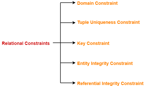


  1. Domain constraint
  2. Tuple Uniqueness constraint
  3. Key constraint
  4. Entity Integrity constraint
  5. Referential Integrity constraint


1. Domain Constraint-


  • Domain constraint defines the domain or set of values for an attribute.
  • It specifies that the value taken by the attribute must be the atomic value from its domain.


Example-


Consider the following Student table-


STU_ID Name Age
S001 Akshay 20
S002 Abhishek 21
S003 Shashank 20
S004 Rahul A


Here, value ‘A’ is not allowed since only integer values can be taken by the age attribute.


2. Tuple Uniqueness Constraint-


Tuple Uniqueness constraint specifies that all the tuples must be necessarily unique in any relation.


Example-01:


Consider the following Student table-


STU_ID Name Age
S001 Akshay 20
S002 Abhishek 21
S003 Shashank 20
S004 Rahul 20


This relation satisfies the tuple uniqueness constraint since here all the tuples are unique.


Example-02:


Consider the following Student table-


STU_ID Name Age
S001 Akshay 20
S001 Akshay 20
S003 Shashank 20
S004 Rahul 20


This relation does not satisfy the tuple uniqueness constraint since here all the tuples are not unique.


3. Key Constraint-


Key constraint specifies that in any relation-

  • All the values of primary key must be unique.
  • The value of primary key must not be null.


Example-


Consider the following Student table-


STU_ID Name Age
S001 Akshay 20
S001 Abhishek 21
S003 Shashank 20
S004 Rahul 20


This relation does not satisfy the key constraint as here all the values of primary key are not unique.


4. Entity Integrity Constraint-


  • Entity integrity constraint specifies that no attribute of primary key must contain a null value in any relation.
  • This is because the presence of null value in the primary key violates the uniqueness property.


Example-


Consider the following Student table-


STU_ID Name Age
S001 Akshay 20
S002 Abhishek 21
S003 Shashank 20
Rahul 20


This relation does not satisfy the entity integrity constraint as here the primary key contains a NULL value.


5. Referential Integrity Constraint-


  • This constraint is enforced when a foreign key references the primary key of a relation.
  • It specifies that all the values taken by the foreign key must either be available in the relation of the primary key or be null.


Read more- Foreign Key in DBMS


Important Results-


The following two important results emerges out due to referential integrity constraint-

  • We can not insert a record into a referencing relation if the corresponding record does not exist in the referenced relation.
  • We can not delete or update a record of the referenced relation if the corresponding record exists in the referencing relation.


Example-


Consider the following two relations- ‘Student’ and ‘Department’.

Here, relation ‘Student’ references the relation ‘Department’.


Student

STU_ID Name Dept_no
S001 Akshay D10
S002 Abhishek D10
S003 Shashank D11
 S004 Rahul D14 


Department

Dept_no Dept_name
D10 ASET
D11 ALS
D12 ASFL
D13 ASHS


Here,

  • The relation ‘Student’ does not satisfy the referential integrity constraint.
  • This is because in relation ‘Department’, no value of primary key specifies department no. 14.
  • Thus, referential integrity constraint is violated.


Handling Violation of Referential Integrity Constraint-


To ensure the correctness of the database, it is important to handle the violation of referential integrity constraint properly.


Next Article- Handling Violation of Referential Integrity Constraint


Get more notes and other study material of Database Management System (DBMS).

Watch video lectures by visiting our YouTube channel LearnVidFun.

Referential Integrity Constraint | Violation

Referential Integrity Constraint-


Before you go through this article, make sure that you have gone through the previous article on Constraints in DBMS.


We have discussed-

  • Relational constraints impose the restrictions on the database to ensure the correctness of data.
  • There are following 5 different types of relational constraints-


  • Referential Integrity constraint is enforced when a foreign key references the primary key of a relation.
  • It specifies that all the values taken by the foreign key must either be available in the relation of the primary key or be null.


Also read- Foreign Key in DBMS


Referential Integrity Constraint Violation-


There are following three possible causes of violation of referential integrity constraint-


Cause-01: Insertion in a referencing relation

Cause-02: Deletion from a referenced relation

Cause-03: Updation in a referenced relation


Cause-01: Insertion in a Referencing Relation-


  • It is allowed to insert only those values in the referencing attribute which are already present in the value of the referenced attribute.
  • Inserting a value in the referencing attribute which is not present in the value of the referenced attribute violates the referential integrity constraint.


Example-


Consider the following two schemas-


Here, relation “Student” references the relation “Branch”.


Student

Roll_no Name Age Branch_Code
1 Rahul 22 CS
2 Anjali 21 CS
3 Teena 20 IT


Branch

Branch_Code Branch_Name
CS Computer Science
EE Electronics Engineering
IT Information Technology
CE Civil Engineering


Here,

  • In relation “Student”, we can not insert any student having branch code ME (Mechanical Engineering).
  • This is because branch code ME is not present in the relation “Branch”.


Cause-02: Deletion from a Referenced Relation-


  • It is not allowed to delete a row from the referenced relation if the referencing attribute uses the value of the referenced attribute of that row.
  • Such a deletion violates the referential integrity constraint.


Example-


Consider the above two relations,

  • We can not delete a tuple from the relation “Branch” having branch code ‘CS’.
  • This is because the referencing attribute “Branch_Code” of the referencing relation “Student” references the value ‘CS’.
  • However, we can safely delete a tuple from the relation “Branch” having branch code ‘CE’.
  • This is because the referencing attribute “Branch_Code” of the referencing relation “Student” does not uses this value.


Handling the Violation-


The violation caused due to a deletion from the referenced relation can be handled in the following three ways-


Method-01:


  • This method involves simultaneously deleting those tuples from the referencing relation where the referencing attribute uses the value of referenced attribute being deleted.
  • This method of handling the violation is called as On Delete Cascade.


Method-02:


  • This method involves aborting or deleting the request for a deletion from the referenced relation if the value is used by the referencing relation.


Method-03:


  • This method involves setting the value being deleted from the referenced relation to NULL or some other value in the referencing relation if the referencing attribute uses that value.


Cause-03: Updation in a Referenced Relation-


  • It is not allowed to update a row of the referenced relation if the referencing attribute uses the value of the referenced attribute of that row.
  • Such an updation violates the referential integrity constraint.


Example-


Consider the above relation.

  • We can not update a tuple in the relation “Branch” having branch code ‘CS’ to the branch code ‘CSE’.
  • This is because referencing attribute “Branch_Code” of the referencing relation “Student” references the value ‘CS’.


Handling the Violation-


The violation caused due to an updation in the referenced relation can be handled in the following three ways-


Method-01:


  • This method involves simultaneously updating those tuples of the referencing relation where the referencing attribute uses the referenced attribute value being updated.
  • This method of handling the violation is called as On Update Cascade.


Method-02:


  • This method involves aborting or deleting the request for an updation of the referenced relation if the value is used by the referencing relation.


Method-03:


  • This method involves setting the value being updated in the referenced relation to NULL or some other value in the referencing relation if the referencing attribute uses that value.


Next Article- Closure of an Attribute Set


Get more notes and other study material of Database Management System (DBMS).

Watch video lectures by visiting our YouTube channel LearnVidFun.
ER Diagrams to Tables

Converting ER Diagrams to Tables-


After designing an ER Diagram,

  • ER diagram is converted into the tables in relational model.
  • This is because relational models can be easily implemented by RDBMS like MySQL , Oracle etc.


Following rules are used for converting an ER diagram into the tables-


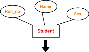
Rule-01: For Strong Entity Set With Only Simple Attributes-


A strong entity set with only simple attributes will require only one table in relational model.

  • Attributes of the table will be the attributes of the entity set.
  • The primary key of the table will be the key attribute of the entity set.


Example-


Roll_no Name Sex


Schema : Student ( Roll_no , Name , Sex )


Also Read- Entity Sets in DBMS


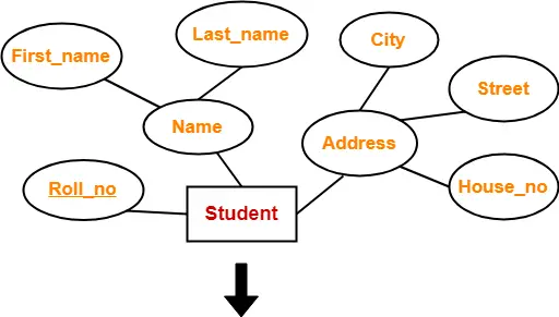
Rule-02: For Strong Entity Set With Composite Attributes-


  • A strong entity set with any number of composite attributes will require only one table in relational model.
  • While conversion, simple attributes of the composite attributes are taken into account and not the composite attribute itself.


Example-


Roll_no First_name Last_name House_no Street City


Schema : Student ( Roll_no , First_name , Last_name , House_no , Street , City )


Also Read- Types of Attributes in DBMS


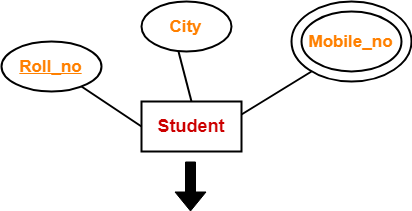
Rule-03: For Strong Entity Set With Multi Valued Attributes-


A strong entity set with any number of multi valued attributes will require two tables in relational model.

  • One table will contain all the simple attributes with the primary key.
  • Other table will contain the primary key and all the multi valued attributes.


Example-


Roll_no City


Roll_no Mobile_no


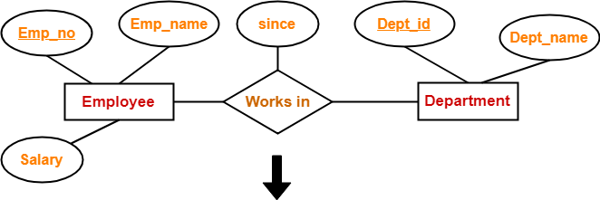
Rule-04: Translating Relationship Set into a Table-


A relationship set will require one table in the relational model.

Attributes of the table are-

  • Primary key attributes of the participating entity sets
  • Its own descriptive attributes if any.

Set of non-descriptive attributes will be the primary key.


Example-


Emp_no Dept_id since


Schema : Works in ( Emp_no , Dept_id , since )


NOTE-


If we consider the overall ER diagram, three tables will be required in relational model-

  • One table for the entity set “Employee”
  • One table for the entity set “Department”
  • One table for the relationship set “Works in”


Rule-05: For Binary Relationships With Cardinality Ratios-


The following four cases are possible-


Case-01: Binary relationship with cardinality ratio m:n

Case-02: Binary relationship with cardinality ratio 1:n

Case-03: Binary relationship with cardinality ratio m:1

Case-04: Binary relationship with cardinality ratio 1:1


Also read- Cardinality Ratios in DBMS


Case-01: For Binary Relationship With Cardinality Ratio m:n


Here, three tables will be required-

  1. A ( a1 , a2 )
  2. R ( a1 , b1 )
  3. B ( b1 , b2 )


Case-02: For Binary Relationship With Cardinality Ratio 1:n


Here, two tables will be required-

  1. A ( a1 , a2 )
  2. BR ( a1 , b1 , b2 )


NOTE- Here, combined table will be drawn for the entity set B and relationship set R.


Case-03: For Binary Relationship With Cardinality Ratio m:1


Here, two tables will be required-

  1. AR ( a1 , a2 , b1 )
  2. B ( b1 , b2 )


NOTE- Here, combined table will be drawn for the entity set A and relationship set R.


Case-04: For Binary Relationship With Cardinality Ratio 1:1


Here, two tables will be required. Either combine ‘R’ with ‘A’ or ‘B’


Way-01:

  1. AR ( a1 , a2 , b1 )
  2. B ( b1 , b2 )


Way-02:

  1. A ( a1 , a2 )
  2. BR ( a1 , b1 , b2 )


Thumb Rules to Remember


While determining the minimum number of tables required for binary relationships with given cardinality ratios, following thumb rules must be kept in mind-

  • For binary relationship with cardinality ration m : n , separate and individual tables will be drawn for each entity set and relationship.
  • For binary relationship with cardinality ratio either m : 1 or 1 : n , always remember “many side will consume the relationship” i.e. a combined table will be drawn for many side entity set and relationship set.
  • For binary relationship with cardinality ratio 1 : 1 , two tables will be required. You can combine the relationship set with any one of the entity sets.


Rule-06: For Binary Relationship With Both Cardinality Constraints and Participation Constraints-


  • Cardinality constraints will be implemented as discussed in Rule-05.
  • Because of the total participation constraint, foreign key acquires NOT NULL constraint i.e. now foreign key can not be null.


Case-01: For Binary Relationship With Cardinality Constraint and Total Participation Constraint From One Side-


Because cardinality ratio = 1 : n , so we will combine the entity set B and relationship set R.

Then, two tables will be required-

  1. A ( a1 , a2 )
  2. BR ( a1 , b1 , b2 )

Because of total participation, foreign key a1 has acquired NOT NULL constraint, so it can’t be null now.


Case-02: For Binary Relationship With Cardinality Constraint and Total Participation Constraint From Both Sides-


If there is a key constraint from both the sides of an entity set with total participation, then that binary relationship is represented using only single table.


Here, Only one table is required.

  • ARB ( a1 , a2 , b1 , b2 )


Rule-07: For Binary Relationship With Weak Entity Set-


Weak entity set always appears in association with identifying relationship with total participation constraint.


Here, two tables will be required-

  1. A ( a1 , a2 )
  2. BR ( a1 , b1 , b2 )


Next Article- Practice Problems On Converting ER Diagrams to Tables


Get more notes and other study material of Database Management System (DBMS).

Watch video lectures by visiting our YouTube channel LearnVidFun.
Canonical Cover in DBMS

Canonical Cover in DBMS-


Before you go through this article, make sure that you have gone through the previous article on Functional Dependency in DBMS.


In DBMS,

  • A canonical cover is a simplified and reduced version of the given set of functional dependencies.
  • Since it is a reduced version, it is also called as Irreducible set.


Characteristics-


  • Canonical cover is free from all the extraneous functional dependencies.
  • The closure of canonical cover is same as that of the given set of functional dependencies.
  • Canonical cover is not unique and may be more than one for a given set of functional dependencies.


Need-


  • Working with the set containing extraneous functional dependencies increases the computation time.
  • Therefore, the given set is reduced by eliminating the useless functional dependencies.
  • This reduces the computation time and working with the irreducible set becomes easier.


Steps To Find Canonical Cover-


Step-01:


Write the given set of functional dependencies in such a way that each functional dependency contains exactly one attribute on its right side.


Example-


The functional dependency X → YZ will be written as-

X → Y

X → Z


Step-02:


  • Consider each functional dependency one by one from the set obtained in Step-01.
  • Determine whether it is essential or non-essential.


To determine whether a functional dependency is essential or not, compute the closure of its left side-

  • Once by considering that the particular functional dependency is present in the set
  • Once by considering that the particular functional dependency is not present in the set


Then following two cases are possible-


Case-01: Results Come Out to be Same-


If results come out to be same,

  • It means that the presence or absence of that functional dependency does not create any difference.
  • Thus, it is non-essential.
  • Eliminate that functional dependency from the set.


NOTE-


  • Eliminate the non-essential functional dependency from the set as soon as it is discovered.
  • Do not consider it while checking the essentiality of other functional dependencies.


Case-01: Results Come Out to be Different-


If results come out to be different,

  • It means that the presence or absence of that functional dependency creates a difference.
  • Thus, it is essential.
  • Do not eliminate that functional dependency from the set.
  • Mark that functional dependency as essential.


Step-03:


  • Consider the newly obtained set of functional dependencies after performing Step-02.
  • Check if there is any functional dependency that contains more than one attribute on its left side.


Then following two cases are possible-


Case-01: No-


  • There exists no functional dependency containing more than one attribute on its left side.
  • In this case, the set obtained in Step-02 is the canonical cover.


Case-01: Yes-


  • There exists at least one functional dependency containing more than one attribute on its left side.
  • In this case, consider all such functional dependencies one by one.
  • Check if their left side can be reduced.


Use the following steps to perform a check-

  • Consider a functional dependency.
  • Compute the closure of all the possible subsets of the left side of that functional dependency.
  • If any of the subsets produce the same closure result as produced by the entire left side, then replace the left side with that subset.

After this step is complete, the set obtained is the canonical cover.


PRACTICE PROBLEM BASED ON FINDING CANONICAL COVER-


Problem-


The following functional dependencies hold true for the relational scheme R ( W , X , Y , Z ) –

X → W

WZ → XY

Y → WXZ

Write the irreducible equivalent for this set of functional dependencies.


Solution-


Step-01:


Write all the functional dependencies such that each contains exactly one attribute on its right side-

X → W

WZ → X

WZ → Y

Y → W

Y → X

Y → Z


Step-02:


Check the essentiality of each functional dependency one by one.


For X → W:


  • Considering X → W, (X)+ = { X , W }
  • Ignoring X → W, (X)+ = { X }


Now,

  • Clearly, the two results are different.
  • Thus, we conclude that X → W is essential and can not be eliminated.


For WZ → X:


  • Considering WZ → X, (WZ)+ = { W , X , Y , Z }
  • Ignoring WZ → X, (WZ)+ = { W , X , Y , Z }


Now,

  • Clearly, the two results are same.
  • Thus, we conclude that WZ → X is non-essential and can be eliminated.


Eliminating WZ → X, our set of functional dependencies reduces to-

X → W

WZ → Y

Y → W

Y → X

Y → Z

Now, we will consider this reduced set in further checks.


For WZ → Y:


  • Considering WZ → Y, (WZ)+ = { W , X , Y , Z }
  • Ignoring WZ → Y, (WZ)+ = { W , Z }


Now,

  • Clearly, the two results are different.
  • Thus, we conclude that WZ → Y is essential and can not be eliminated.


For Y → W:


  • Considering Y → W, (Y)+ = { W , X , Y , Z }
  • Ignoring Y → W, (Y)+ = { W , X , Y , Z }


Now,

  • Clearly, the two results are same.
  • Thus, we conclude that Y → W is non-essential and can be eliminated.


Eliminating Y → W, our set of functional dependencies reduces to-

X → W

WZ → Y

Y → X

Y → Z


For Y → X:


  • Considering Y → X, (Y)+ = { W , X , Y , Z }
  • Ignoring Y → X, (Y)+ = { Y , Z }


Now,

  • Clearly, the two results are different.
  • Thus, we conclude that Y → X is essential and can not be eliminated.


For Y → Z:


  • Considering Y → Z, (Y)+ = { W , X , Y , Z }
  • Ignoring Y → Z, (Y)+ = { W , X , Y }


Now,

  • Clearly, the two results are different.
  • Thus, we conclude that Y → Z is essential and can not be eliminated.


From here, our essential functional dependencies are-

X → W

WZ → Y

Y → X

Y → Z


Step-03:


  • Consider the functional dependencies having more than one attribute on their left side.
  • Check if their left side can be reduced.


In our set,

  • Only WZ → Y contains more than one attribute on its left side.
  • Considering WZ → Y, (WZ)+ = { W , X , Y , Z }


Now,

  • Consider all the possible subsets of WZ.
  • Check if the closure result of any subset matches to the closure result of WZ.

(W)+ = { W }

(Z)+ = { Z }


Clearly,

  • None of the subsets have the same closure result same as that of the entire left side.
  • Thus, we conclude that we can not write WZ → Y as W → Y or Z → Y.
  • Thus, set of functional dependencies obtained in step-02 is the canonical cover.


Finally, the canonical cover is-

X → W

WZ → Y

Y → X

Y → Z

Canonical Cover


Next Article- Decomposition of a Relation


Get more notes and other study material of Database Management System (DBMS).

Watch video lectures by visiting our YouTube channel LearnVidFun.
Types of Keys in DBMS | Definitions | Examples

Keys in DBMS-


A key is a set of attributes that can identify each tuple uniquely in the given relation.


Also read- Attributes in DBMS


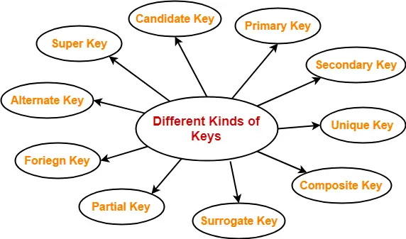
Different Types Of Keys in DBMS-


There are following 10 important keys in DBMS-


  1. Super key
  2. Candidate key
  3. Primary key
  4. Alternate key
  5. Foreign key
  6. Partial key
  7. Composite key
  8. Unique key
  9. Surrogate key
  10. Secondary key


NOTE-


Before proceeding further, Kindly note-

  • The terms ‘relation’ and ‘table’ are used interchangeably.
  • The terms ‘tuple’ and ‘record’ are used interchangeably.

So, don’t get confused!


1. Super Key-


  • A super key is a set of attributes that can identify each tuple uniquely in the given relation.
  • A super key is not restricted to have any specific number of attributes.
  • Thus, a super key may consist of any number of attributes.


Example-


Consider the following Student schema-

Student ( roll , name , sex , age , address , class , section )


Given below are the examples of super keys since each set can uniquely identify each student in the Student table-

  • ( roll , name , sex , age , address , class , section )
  • ( class , section , roll )
  • (class , section , roll , sex )
  • ( name , address )


NOTE-


All the attributes in a super key are definitely sufficient to identify each tuple uniquely in the given relation but all of them may not be necessary.


2. Candidate Key-


A minimal super key is called as a candidate key.

OR

A set of minimal attribute(s) that can identify each tuple uniquely in the given relation is called as a candidate key.


Example-


Consider the following Student schema-

Student ( roll , name , sex , age , address , class , section )


Given below are the examples of candidate keys since each set consists of minimal attributes required to identify each student uniquely in the Student table-

  • ( class , section , roll )
  • ( name , address )


NOTES-


  • All the attributes in a candidate key are sufficient as well as necessary to identify each tuple uniquely.
  • Removing any attribute from the candidate key fails in identifying each tuple uniquely.
  • The value of candidate key must always be unique.
  • The value of candidate key can never be NULL.
  • It is possible to have multiple candidate keys in a relation.
  • Those attributes which appears in some candidate key are called as prime attributes.


3. Primary Key-


A primary key is a candidate key that the database designer selects while designing the database.

OR

Candidate key that the database designer implements is called as a primary key.


NOTES-


  • The value of primary key can never be NULL.
  • The value of primary key must always be unique.
  • The values of primary key can never be changed i.e. no updation is possible.
  • The value of primary key must be assigned when inserting a record.
  • A relation is allowed  to have only one primary key.


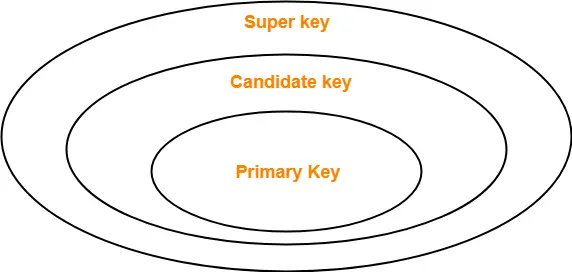
Remember-


4. Alternate Key-


Candidate keys that are left unimplemented or unused after implementing the primary key are called as alternate keys.

OR

Unimplemented candidate keys are called as alternate keys.


5. Foreign Key-


  • An attribute ‘X’ is called as a foreign key to some other attribute ‘Y’ when its values are dependent on the values of attribute ‘Y’.
  • The attribute ‘X’ can assume only those values which are assumed by the attribute ‘Y’.
  • Here, the relation in which attribute ‘Y’ is present is called as the referenced relation.
  • The relation in which attribute ‘X’ is present is called as the referencing relation.
  • The attribute ‘Y’ might be present in the same table or in some other table.


Example-


Consider the following two schemas-


Here, t_dept can take only those values which are present in dept_no in Department table since only those departments actually exist.


NOTES-


  • Foreign key references the primary key of the table.
  • Foreign key can take only those values which are present in the primary key of the referenced relation.
  • Foreign key may have a name other than that of a primary key.
  • Foreign key can take the NULL value.
  • There is no restriction on a foreign key to be unique.
  • In fact, foreign key is not unique most of the time.
  • Referenced relation may also be called as the master table or primary table.
  • Referencing relation may also be called as the foreign table.


6. Partial Key-


  • Partial key is a key using which all the records of the table can not be identified uniquely.
  • However, a bunch of related tuples can be selected from the table using the partial key.


Example-


Consider the following schema-

Department ( Emp_no , Dependent_name , Relation )


Emp_no Dependent_name Relation
E1 Suman Mother
E1 Ajay Father
E2 Vijay Father
E2 Ankush Son


Here, using partial key Emp_no, we can not identify a tuple uniquely but we can select a bunch of tuples from the table.


7. Composite Key-


A primary key comprising of multiple attributes and not just a single attribute is called as a composite key.


8. Unique Key-


Unique key is a key with the following properties-

  • It is unique for all the records of the table.
  • Once assigned, its value can not be changed i.e. it is non-updatable.
  • It may have a NULL value.


Example-


The best example of unique key is Adhaar Card Numbers.

  • The Adhaar Card Number is unique for all the citizens (tuples) of India (table).
  • If it gets lost and another duplicate copy is issued, then the duplicate copy always has the same number as before.
  • Thus, it is non-updatable.
  • Few citizens may not have got their Adhaar cards, so for them its value is NULL.


9. Surrogate Key-


Surrogate key is a key with the following properties-

  • It is unique for all the records of the table.
  • It is updatable.
  • It can not be NULL i.e. it must have some value.


Example-


Mobile Number of students in a class where every student owns a mobile phone.


10. Secondary Key-


Secondary key is required for the indexing purpose for better and faster searching.


Next Article- Finding Candidate Keys of Given Relation


Get more notes and other study material of Database Management System (DBMS).

Watch video lectures by visiting our YouTube channel LearnVidFun.