Category: Database Management System

ER Diagrams | ER Diagram Symbols

ER diagram-


  • ER diagram or Entity Relationship diagram is a conceptual model that gives the graphical representation of the logical structure of the database.
  • It shows all the constraints and relationships that exist among the different components.


Components of ER diagram-


An ER diagram is mainly composed of following three components-

  1. Entity Sets
  2. Attributes
  3. Relationship Set


Example-


Consider the following Student table-


Roll_no Name Age
1 Akshay 20
2 Rahul 19
3 Pooja 20
4 Aarti 19


This complete table is referred to as “Student Entity Set” and each row represents an “entity”.


Representation as ER Diagram-


The above table may be represented as ER diagram as-
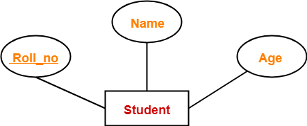


Here,

  • Roll_no is a primary key that can identify each entity uniquely.
  • Thus, by using student’s roll number, a student can be identified uniquely.


ER Diagram Symbols-


An ER diagram is composed of several components and each component in ER diagram is represented using a specific symbol.

ER diagram symbols are discussed below-


1. For Entity Sets-


An entity set is a set of same type of entities.

An entity refers to any object having-

  • Either a physical existence such as a particular person, office, house or car.
  • Or a conceptual existence such as a school or a company.


An entity set may be of the following two types-
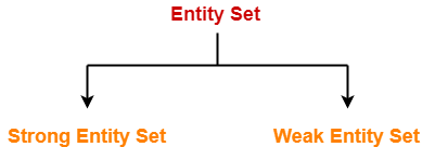


  1. Strong entity set
  2. Weak entity set


1. Strong Entity Set-


  • A strong entity set possess its own primary key.
  • It is represented using a single rectangle.


2. Weak Entity Set-


  • A weak entity set do not possess its own primary key.
  • It is represented using a double rectangle.


Read more- Entity Sets in DBMS


2. For Relationship Sets-


  • Relationship defines an association among several entities.
  • A relationship set is a set of same type of relationships.


A relationship set may be of the following two types-


  1. Strong relationship set
  2. Weak relationship set


1. Strong Relationship Set-


  • A strong relationship exists between two strong entity sets.
  • It is represented using a diamond symbol.


2. Weak Relationship Set-


  • A weak or identifying relationship exists between the strong and weak entity set.
  • It is represented using a double diamond symbol.


Read more- Relationship Sets in DBMS


3. For Attributes-


  • Attributes are the properties which describes the entities of an entity set.
  • There are several types of attributes.
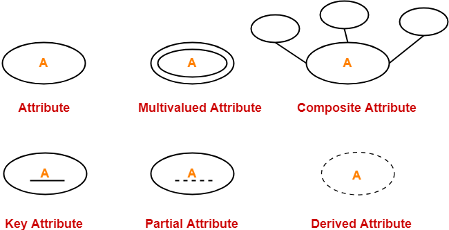


Read more- Attributes in ER Diagram


4. For Participation Constraints-


Participation constraint defines the least number of relationship instances in which an entity has to necessarily participate.

There are two types of participation constraints-


  1. Partial participation
  2. Total participation


1. Partial Participation-


Partial participation is represented using a single line between the entity set and relationship set.


2. Total Participation-


Total participation is represented using a double line between the entity set and relationship set.


Read more- Participation Constraints in DBMS


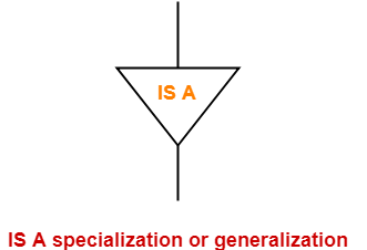
5. For Specialization and Generalization-


  • Generalization is a process of forming a generalized super class by extracting the common characteristics from two or more classes.
  • Specialization is a reverse process of generalization where a super class is divided into sub classes by assigning the specific characteristics of sub classes to them.


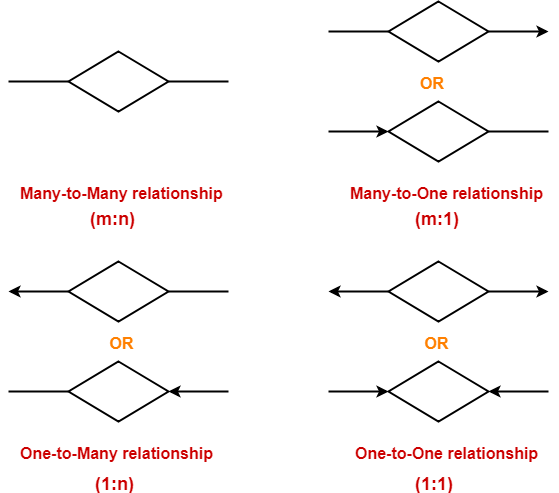
6. For Cardinality Constraints / Ratios-


Cardinality constraint defines the maximum number of relationship instances in which an entity can participate.

There are 4 types of cardinality ratios-
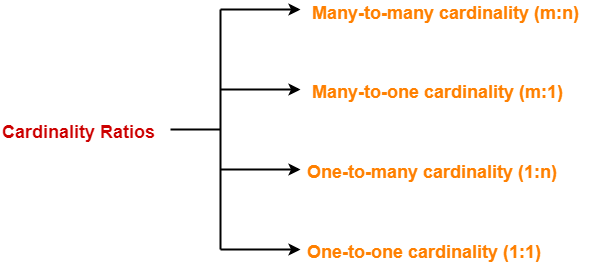


  1. Many-to-many cardinality (m:n)
  2. Many-to-one cardinality (m:1)
  3. One-to-many cardinality (1:n)
  4. One-to-one cardinality (1:1)


Read more- Cardinality Ratios in DBMS

Next Article- Entity Sets in DBMS


Get more notes and other study material of Database Management System (DBMS).

Watch video lectures by visiting our YouTube channel LearnVidFun.

Entity Sets in DBMS

Entity Set in DBMS-


Before you go through this article, make sure that you have gone through the previous article on Introduction to ER Diagrams.


An entity set is a set of same type of entities.


An entity refers to any object having-

  • Either a physical existence such as a particular person, office, house or car.
  • Or a conceptual existence such as a school, a university, a company or a job.


In ER diagram,

  • Attributes are associated with an entity set.
  • Attributes describe the properties of entities in the entity set.
  • Based on the values of certain attributes, an entity can be identified uniquely.


Types of Entity Sets-


An entity set may be of the following two types-


  1. Strong entity set
  2. Weak entity set


1. Strong Entity Set-


  • A strong entity set is an entity set that contains sufficient attributes to uniquely identify all its entities.
  • In other words, a primary key exists for a strong entity set.
  • Primary key of a strong entity set is represented by underlining it.


Symbols Used-


  • A single rectangle is used for representing a strong entity set.
  • A diamond symbol is used for representing the relationship that exists between two strong entity sets.
  • A single line is used for representing the connection of the strong entity set with the relationship set.
  • A double line is used for representing the total participation of an entity set with the relationship set.
  • Total participation may or may not exist in the relationship.


Example-


Consider the following ER diagram-


In this ER diagram,


  • Two strong entity sets “Student” and “Course” are related to each other.
  • Student ID and Student name are the attributes of entity set “Student”.
  • Student ID is the primary key using which any student can be identified uniquely.
  • Course ID and Course name are the attributes of entity set “Course”.
  • Course ID is the primary key using which any course can be identified uniquely.
  • Double line between Student and relationship set signifies total participation.
  • It suggests that each student must be enrolled in at least one course.
  • Single line between Course and relationship set signifies partial participation.
  • It suggests that there might exist some courses for which no enrollments are made.


2. Weak Entity Set-


  • A weak entity set is an entity set that does not contain sufficient attributes to uniquely identify its entities.
  • In other words, a primary key does not exist for a weak entity set.
  • However, it contains a partial key called as a discriminator.
  • Discriminator can identify a group of entities from the entity set.
  • Discriminator is represented by underlining with a dashed line.


NOTE-


  • The combination of discriminator and primary key of the strong entity set makes it possible to uniquely identify all entities of the weak entity set.
  • Thus, this combination serves as a primary key for the weak entity set.
  • Clearly, this primary key is not formed by the weak entity set completely.


Symbols Used-


  • A double rectangle is used for representing a weak entity set.
  • A double diamond symbol is used for representing the relationship that exists between the strong and weak entity sets and this relationship is known as identifying relationship.
  • A double line is used for representing the connection of the weak entity set with the relationship set.
  • Total participation always exists in the identifying relationship.


Example-


Consider the following ER diagram-


In this ER diagram,


  • One strong entity set “Building” and one weak entity set “Apartment” are related to each other.
  • Strong entity set “Building” has building number as its primary key.
  • Door number is the discriminator of the weak entity set “Apartment”.
  • This is because door number alone can not identify an apartment uniquely as there may be several other buildings having the same door number.
  • Double line between Apartment and relationship set signifies total participation.
  • It suggests that each apartment must be present in at least one building.
  • Single line between Building and relationship set signifies partial participation.
  • It suggests that there might exist some buildings which has no apartment.


To uniquely identify any apartment,

  • First, building number is required to identify the particular building.
  • Secondly, door number of the apartment is required to uniquely identify the apartment.


Thus,

Primary key of Apartment

= Primary key of Building + Its own discriminator

= Building number + Door number


Differences between Strong entity set and Weak entity set-


Strong entity set Weak entity set
A single rectangle is used for the representation of a strong entity set. A double rectangle is used for the representation of a weak entity set.
It contains sufficient attributes to form its primary key. It does not contain sufficient attributes to form its primary key.
A diamond symbol is used for the representation of the relationship that exists between the two strong entity sets. A double diamond symbol is used for the representation of the identifying relationship that exists between the strong and weak entity set.
A single line is used for the representation of the connection between the strong entity set and the relationship. A double line is used for the representation of the connection between the weak entity set and the relationship set.
Total participation may or may not exist in the relationship. Total participation always exists in the identifying relationship.


Important Note-


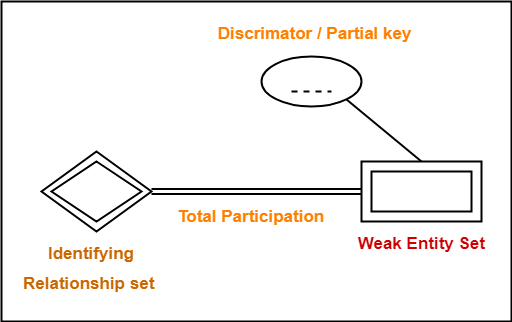
In ER diagram, weak entity set is always present in total participation with the identifying relationship set.

So, we always have the picture like shown here-


Next Article- Relationship Sets in DBMS


Get more notes and other study material of Database Management System (DBMS).

Watch video lectures by visiting our YouTube channel LearnVidFun.

Schedules in DBMS | Types of Schedules in DBMS

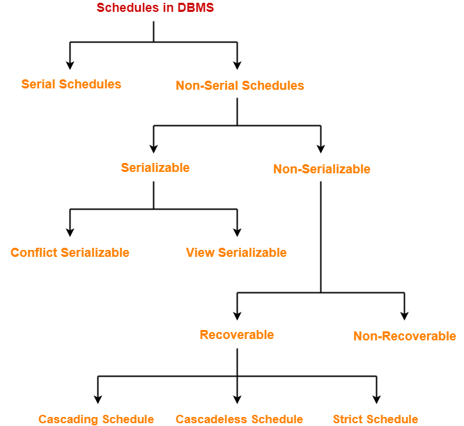
Schedules in DBMS-


Before you go through this article, make sure that you have gone through the previous article on Transactions in DBMS.


The order in which the operations of multiple transactions appear for execution is called as a schedule.


Types of Schedules-


In DBMS, schedules may be classified as-


In this article, we will discuss about Serial and Non-Serial Schedules.


Serial Schedules-


In serial schedules,

  • All the transactions execute serially one after the other.
  • When one transaction executes, no other transaction is allowed to execute.


Characteristics-


Serial schedules are always-

  • Consistent
  • Recoverable
  • Cascadeless
  • Strict


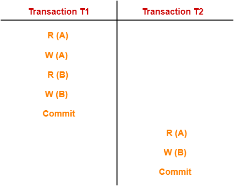
Example-01:


In this schedule,

  • There are two transactions T1 and T2 executing serially one after the other.
  • Transaction T1 executes first.
  • After T1 completes its execution, transaction T2 executes.
  • So, this schedule is an example of a Serial Schedule.


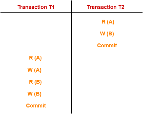
Example-02:


In this schedule,

  • There are two transactions T1 and T2 executing serially one after the other.
  • Transaction T2 executes first.
  • After T2 completes its execution, transaction T1 executes.
  • So, this schedule is an example of a Serial Schedule.


Non-Serial Schedules-


In non-serial schedules,

  • Multiple transactions execute concurrently.
  • Operations of all the transactions are inter leaved or mixed with each other.


Characteristics-


Non-serial schedules are NOT always-

  • Consistent
  • Recoverable
  • Cascadeless
  • Strict


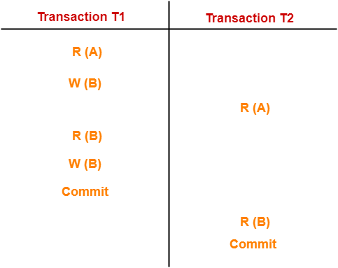
Example-01:


In this schedule,

  • There are two transactions T1 and T2 executing concurrently.
  • The operations of T1 and T2 are interleaved.
  • So, this schedule is an example of a Non-Serial Schedule.


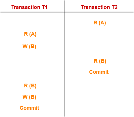
Example-02:


In this schedule,

  • There are two transactions T1 and T2 executing concurrently.
  • The operations of T1 and T2 are interleaved.
  • So, this schedule is an example of a Non-Serial Schedule.


Finding Number Of Schedules-


Consider there are n number of transactions T1, T2, T3 …. , Tn with N1, N2, N3 …. , Nn number of operations respectively.


Total Number of Schedules-


Total number of possible schedules (serial + non-serial) is given by-


Total Number of Serial Schedules-


Total number of serial schedules

= Number of different ways of arranging n transactions

= n!


Total Number of Non-Serial Schedules-


Total number of non-serial schedules

= Total number of schedules – Total number of serial schedules


PRACTICE PROBLEM BASED ON FINDING NUMBER OF SCHEDULES-


Problem-


Consider there are three transactions with 2, 3, 4 operations respectively, find-

  1. How many total number of schedules are possible?
  2. How many total number of serial schedules are possible?
  3. How many total number of non-serial schedules are possible?


Solution-


Total Number of Schedules-


Using the above formula, we have-


Total Number of Serial Schedules-


Total number of serial schedules

= Number of different ways of arranging 3 transactions

= 3!

= 6


Total Number of Non-Serial Schedules-


Total number of non-serial schedules

= Total number of schedules – Total number of serial schedules

= 1260 – 6

= 1254


Next Article- Serializability in DBMS


Get more notes and other study material of Database Management System (DBMS).

Watch video lectures by visiting our YouTube channel LearnVidFun.

Transaction States in DBMS

Transaction in DBMS-


“Transaction is a set of operations which are all logically related.”

OR

“Transaction is a single logical unit of work formed by a set of operations.”


Operations in Transaction-


The main operations in a transaction are-

  1. Read Operation
  2. Write Operation


1. Read Operation-


  • Read operation reads the data from the database and then stores it in the buffer in main memory.
  • For example- Read(A) instruction will read the value of A from the database and will store it in the buffer in main memory.


2. Write Operation-


  • Write operation writes the updated data value back to the database from the buffer.
  • For example- Write(A) will write the updated value of A from the buffer to the database.


Transaction States-


A transaction goes through many different states throughout its life cycle.

These states are called as transaction states.

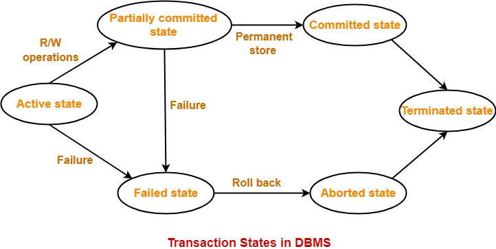
Transaction states are as follows-

  1. Active state
  2. Partially committed state
  3. Committed state
  4. Failed state
  5. Aborted state
  6. Terminated state


1. Active State-


  • This is the first state in the life cycle of a transaction.
  • A transaction is called in an active state as long as its instructions are getting executed.
  • All the changes made by the transaction now are stored in the buffer in main memory.


2. Partially Committed State-


  • After the last instruction of transaction has executed, it enters into a partially committed state.
  • After entering this state, the transaction is considered to be partially committed.
  • It is not considered fully committed because all the changes made by the transaction are still stored in the buffer in main memory.


3. Committed State-


  • After all the changes made by the transaction have been successfully stored into the database, it enters into a committed state.
  • Now, the transaction is considered to be fully committed.


NOTE-


  • After a transaction has entered the committed state, it is not possible to roll back the transaction.
  • In other words, it is not possible to undo the changes that has been made by the transaction.
  • This is because the system is updated into a new consistent state.
  • The only way to undo the changes is by carrying out another transaction called as compensating transaction that performs the reverse operations.


4. Failed State-


  • When a transaction is getting executed in the active state or partially committed state and some failure occurs due to which it becomes impossible to continue the execution, it enters into a failed state.


5. Aborted State-


  • After the transaction has failed and entered into a failed state, all the changes made by it have to be undone.
  • To undo the changes made by the transaction, it becomes necessary to roll back the transaction.
  • After the transaction has rolled back completely, it enters into an aborted state.


6. Terminated State-


  • This is the last state in the life cycle of a transaction.
  • After entering the committed state or aborted state, the transaction finally enters into a terminated state where its life cycle finally comes to an end.


Next Article- ACID Properties of Transaction


Get more notes and other study material of Database Management System (DBMS).

Watch video lectures by visiting our YouTube channel LearnVidFun.
Concurrency Problems | DBMS

Transactions in DBMS-


Before you go through this article, make sure that you have gone through the previous article on Transactions in DBMS.


We have discussed-

  • A transaction is a set of logically related operations.
  • A transaction goes through different states throughout its life cycle.
  • ACID Properties are followed by each transaction to ensure the consistency of database.


In this article, we will discuss about concurrency problems of transactions.


Concurrency Problems in DBMS-


  • When multiple transactions execute concurrently in an uncontrolled or unrestricted manner, then it might lead to several problems.
  • Such problems are called as concurrency problems.


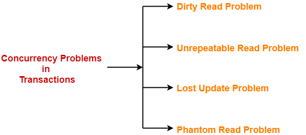
The concurrency problems are-


  1. Dirty Read Problem
  2. Unrepeatable Read Problem
  3. Lost Update Problem
  4. Phantom Read Problem


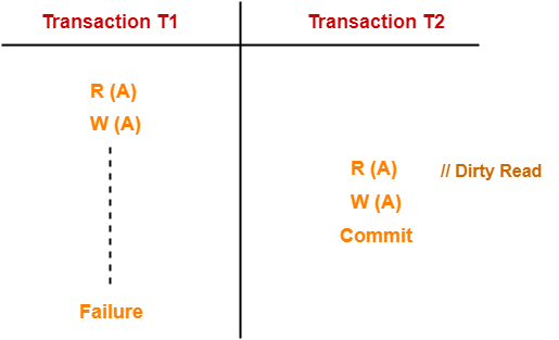
1. Dirty Read Problem-


Reading the data written by an uncommitted transaction is called as dirty read.


This read is called as dirty read because-

  • There is always a chance that the uncommitted transaction might roll back later.
  • Thus, uncommitted transaction might make other transactions read a value that does not even exist.
  • This leads to inconsistency of the database.


NOTE-


  • Dirty read does not lead to inconsistency always.
  • It becomes problematic only when the uncommitted transaction fails and roll backs later due to some reason.


Example-


Here,

  1. T1 reads the value of A.
  2. T1 updates the value of A in the buffer.
  3. T2 reads the value of A from the buffer.
  4. T2 writes the updated the value of A.
  5. T2 commits.
  6. T1 fails in later stages and rolls back.


In this example,

  • T2 reads the dirty value of A written by the uncommitted transaction T1.
  • T1 fails in later stages and roll backs.
  • Thus, the value that T2 read now stands to be incorrect.
  • Therefore, database becomes inconsistent.


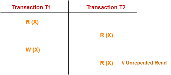
2. Unrepeatable Read Problem-


This problem occurs when a transaction gets to read unrepeated i.e. different values of the same variable in its different read operations even when it has not updated its value.


Example-


Here,

  1. T1 reads the value of X (= 10 say).
  2. T2 reads the value of X (= 10).
  3. T1 updates the value of X (from 10 to 15 say) in the buffer.
  4. T2 again reads the value of X (but = 15).


In this example,

  • T2 gets to read a different value of X in its second reading.
  • T2 wonders how the value of X got changed because according to it, it is running in isolation.


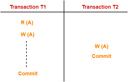
3. Lost Update Problem-


This problem occurs when multiple transactions execute concurrently and updates from one or more transactions get lost.


Example-


Here,

  1. T1 reads the value of A (= 10 say).
  2. T2 updates the value to A (= 15 say) in the buffer.
  3. T2 does blind write A = 25 (write without read) in the buffer.
  4. T2 commits.
  5. When T1 commits, it writes A = 25 in the database.


In this example,

  • T1 writes the over written value of X in the database.
  • Thus, update from T1 gets lost.


NOTE-


  • This problem occurs whenever there is a write-write conflict.
  • In write-write conflict, there are two writes one by each transaction on the same data item without any read in the middle.


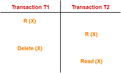
4. Phantom Read Problem-


This problem occurs when a transaction reads some variable from the buffer and when it reads the same variable later, it finds that the variable does not exist.


Example-


Here,

  1. T1 reads X.
  2. T2 reads X.
  3. T1 deletes X.
  4. T2 tries reading X but does not find it.


In this example,

  • T2 finds that there does not exist any variable X when it tries reading X again.
  • T2 wonders who deleted the variable X because according to it, it is running in isolation.


Avoiding Concurrency Problems-


  • To ensure consistency of the database, it is very important to prevent the occurrence of above problems.
  • Concurrency Control Protocols help to prevent the occurrence of above problems and maintain the consistency of the database.


Next Article- Schedules in DBMS


Get more notes and other study material of Database Management System (DBMS).

Watch video lectures by visiting our YouTube channel LearnVidFun.