Category: Computer Networks

Token Passing | Token Ring in Networking

Access Control in Networking-


Before you go through this article, make sure that you have gone through the previous article on Access Control.


We have discussed-

  • Access Control is a mechanism that controls the access of stations to the transmission link.
  • Broadcast links require the access control mechanism.
  • There are various access control methods-
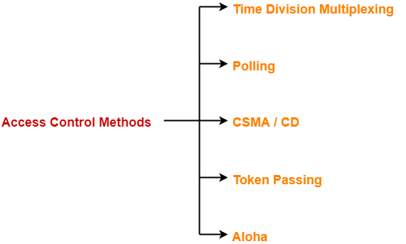


  1. Time Division Multiplexing
  2. Polling
  3. CSMA / CD
  4. Token Passing
  5. Aloha


In this article, we will discuss about Token Passing.


Before discussing Token Passing, let us discuss few important concepts required for the discussion.


Time Conversions-


In token passing,

  • Time may be expressed in seconds, bits or meters.
  • To convert the time from one unit to another, we use the following conversion chart-
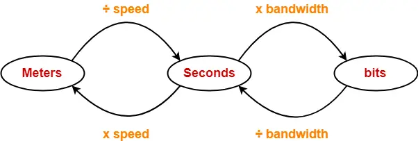


Conversion Chart


Token Passing Terminology-


The following terms are frequently used-

  1. Token
  2. Ring Latency
  3. Cycle Time


1. Token-


  • A token is a small message composed of a special bit pattern.
  • It represents the permission to send the data packet.
  • A station is allowed to transmit a data packet if and only if it possess the token otherwise not.


2. Ring Latency-


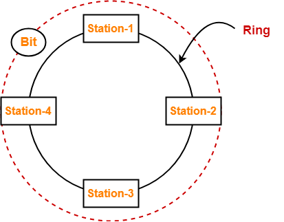
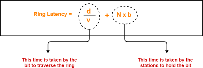
Time taken by a bit to complete one revolution of the ring is called as ring latency.


Let us derive the expression for ring latency.

If-

  • Length of the ring = d
  • Speed of the bit = v
  • Number of stations = N
  • Bit delay at each station = b

(Bit delay is the time for which a station holds the bit before transmitting to the other side)

Then-


Notes-


  • d / v is the propagation delay (Tp) expressed in seconds.
  • Generally, bit delay is expressed in bits.
  • So, both the terms (d / v and N x b) have different units.
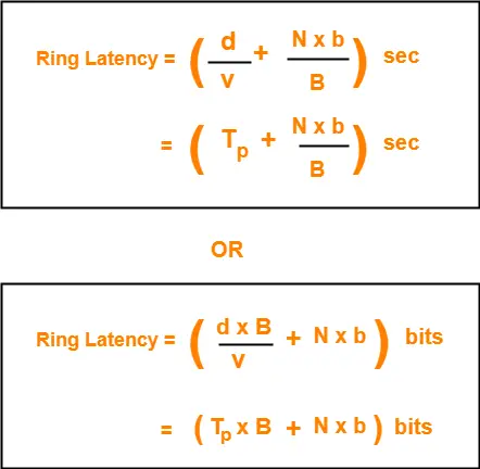
  • While calculating the ring latency, both the terms are brought into the same unit.
  • The above conversion chart is used for conversion.


After conversion, we have-


3. Cycle Time-


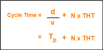
Time taken by the token to complete one revolution of the ring is called as cycle time.


If-

  • Length of the ring = d
  • Speed of the bit = v
  • Number of stations = N
  • Token Holding Time = THT

(Token Holding Time is the time for which a station holds the token before transmitting to the other side)

Then-


Now, we start discussing about Token Passing Access Control Method.


Token Passing-


In this access control method,

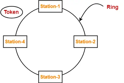
  • All the stations are logically connected to each other in the form of a ring.
  • The access of stations to the transmission link is governed by a token.
  • A station is allowed to transmit a data packet if and only if it possess the token otherwise not.
  • Each station passes the token to its neighboring station either clockwise or anti-clockwise.


Assumptions-


Token passing method assumes-

  • Each station in the ring has the data to send.
  • Each station sends exactly one data packet after acquiring the token.


Efficiency-


Efficiency (η) = Useful Time / Total Time


In one cycle,

  • Useful time = Sum of transmission delay of N stations since each station sends 1 data packet = N x Tt
  • Total Time = Cycle time = Tp + N x THT

Thus,


Token Holding Time depends on the strategy implemented.


Token Passing Strategies-


The following 2 strategies are used in token passing-


  1. Delayed Token Reinsertion (DTR)
  2. Early Token Reinsertion (ETR)


1. Delayed Token Reinsertion-


In this strategy,

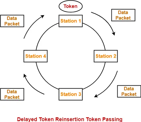
  • Station keeps holding the token until the last bit of the data packet transmitted by it takes the complete revolution of the ring and comes back to it.


Working-


After a station acquires the token,

  • It transmits its data packet.
  • It holds the token until the data packet reaches back to it.
  • After data packet reaches to it, it discards its data packet as its journey is completed.
  • It releases the token.


The following diagram illustrates these steps for station-1. Same procedure is repeated at every station.


Token Holding Time-


Token Holding Time (THT) = Transmission delay + Ring Latency


We know,

  • Ring Latency = Tp + N x bit delay
  • Assuming bit delay = 0 (in most cases), we get-


Token Holding Time = Tt + Tp


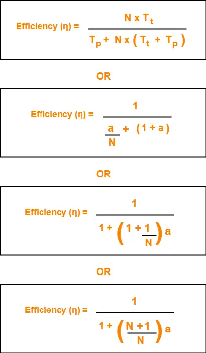
Efficiency-


Substituting THT = Tt + Tp in the efficiency expression, we get-


2. Early Token Reinsertion-


In this strategy,

  • Station releases the token immediately after putting its data packet to be transmitted on the ring.


Working-
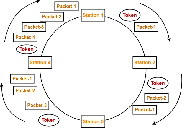


Step-01: At Station-1:


Station-1

  • Acquires the token
  • Transmits packet-1
  • Releases the token


Step-02: At Station-2:


Station-2

  • Receives packet-1
  • Transmits packet-1
  • Acquires the token
  • Transmits packet-2
  • Releases the token


Step-03: At Station-3:


Station-3

  • Receives packet-1
  • Transmits packet-1
  • Receives packet-2
  • Transmits packet-2
  • Acquires the token
  • Transmits packet-3
  • Releases the token


Step-04: At Station-4:


Station-4

  • Receives packet-1
  • Transmits packet-1
  • Receives packet-2
  • Transmits packet-2
  • Receives packet-3
  • Transmits packet-3
  • Acquires the token
  • Transmits packet-4
  • Releases the token


Step-05: At Station-1:


  • Receives packet-1
  • Discards packet-1 (as its journey is completed)
  • Receives packet-2
  • Transmits packet-2
  • Receives packet-3
  • Transmits packet-3
  • Receives packet-4
  • Transmits packet-4
  • Acquires the token
  • Transmits packet-1 (new)
  • Releases the token

In this manner, the cycle continues.


Token Holding Time-


Token Holding Time (THT) = Transmission delay of data packet = Tt


Efficiency-


Substituting THT = Tt in the efficiency expression, we get-


Differences between DTR and ETR-


Delay Token Retransmission (DTR) Early Token Retransmission (ETR)
Each station holds the token until its data packet reaches back to it. Each station releases the token immediately after putting its data packet on the ring.
There exists only one data packet on the ring at any given instance. There exists more than one data packet on the ring at any given instance.
It is more reliable than ETR. It is less reliable than DTR.
It has low efficiency as compared to ETR. It has high efficiency as compared to ETR.


Important Notes-


Note-01:


In token passing,

  • It is the responsibility of each transmitting station to remove its own data packet from the ring.


Note-02:


While solving questions,

  • If the strategy used is not mentioned, then consider Early Token Retransmission strategy.


To gain better understanding about Token Passing Method,

Watch this Video Lecture


Next Article- Practice Problems On Token Passing


Get more notes and other study material of Computer Networks.

Watch video lectures by visiting our YouTube channel LearnVidFun.
Binary Exponential BackOff Algorithm | CSMA CD

CSMA / CD Protocol-


Before you go through this article, make sure that you have gone through the previous article on CSMA / CD Protocol.


We have discussed-

  • CSMA / CD stands for Carrier Sense Multiple Access / Collision Detection.
  • It allows the stations to sense the carrier and transmit data if the carrier is free.


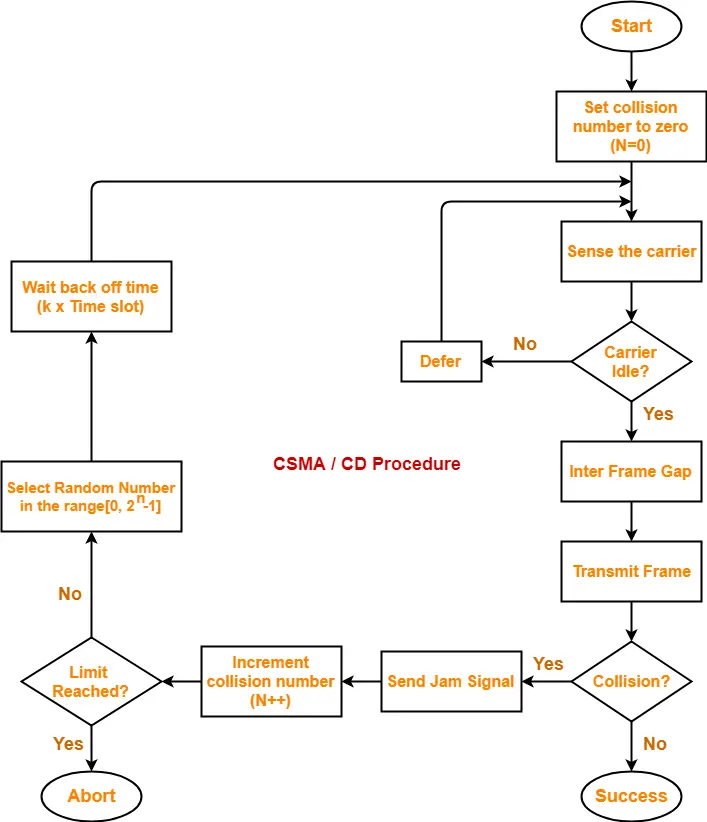
The following CSMA / CD flowchart shows the CSMA / CD procedure-


Back Off Time-


In CSMA / CD protocol,

  • After the occurrence of collision, station waits for some random back off time and then retransmits.
  • This waiting time for which the station waits before retransmitting the data is called as back off time.
  • Back Off Algorithm is used for calculating the back off time.


Back Off Algorithm-


After undergoing the collision,

  • Transmitting station chooses a random number in the range [0, 2n-1] if the packet is undergoing collision for the nth time.
  • If station chooses a number k, then-


Back off time = k x Time slot

where value of one time slot = 1 RTT


Example-


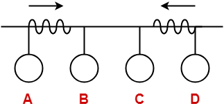
Consider the following scenario where stations A and D start transmitting their data simultaneously-


For simplicity,

  • We consider the value of time slot = 1 unit.
  • Thus, back off time = K units.


Scene-01: For 1st Data Packet Of Both Stations-


  • Both the stations start transmitting their 1st data packet simultaneously.
  • This leads to a collision.
  • Clearly, the collision on both the packets is occurring for the 1st time.
  • So, collision number for the 1st data packet of both the stations = 1.


At Station A-


After detecting the collision,

  • Station A randomly chooses a number in the range [0, 21-1] = [0,1].
  • If station A chooses the number KA, then back off time = KA units.


At Station D-


After detecting the collision,

  • Station D randomly chooses a number in the range [0, 21-1] = [0,1].
  • If station D chooses the number KD, then back off time = KD units.


Following 4 cases are possible-


KA KD Remarks
0 0
  • In this case, both the stations start retransmitting their data immediately.
  • This case leads to a collision again.
0 1
  • In this case, station A starts retransmitting its data immediately while station D waits for 1 unit of time.
  • This case leads to A successfully retransmitting its data after the 1st collision.
1 0
  • In this case, station A waits for 1 unit of time while station D starts retransmitting its data immediately.
  • This case leads to D successfully retransmitting its data after the 1st collision.
1 1
  • In this case, both the stations wait for 1 unit of time and then starts retransmitting their data simultaneously.
  • This case leads to a collision again.


From here,

  • Probability of station A to successfully retransmit its data after the 1st collision = 1 / 4
  • Probability of station D to successfully retransmit its data after the 1st collision = 1 / 4
  • Probability of occurrence of collision again after the 1st collision = 2 / 4 = 1 / 2


Now,

  • Consider case-02 occurs.
  • This causes station A to successfully retransmit its 1st packet after the 1st collision.


Scene-02: For 2nd Data Packet Of Station A And 1st Data Packet Of Station D-


Consider after some time,

  • Station A starts transmitting its 2nd data packet and station D starts retransmitting its 1st data packet simultaneously.
  • This leads to a collision.


At Station A-


  • The 2nd data packet of station A undergoes collision for the 1st time.
  • So, collision number for the 2nd data packet of station A = 1.
  • Now, station A randomly chooses a number in the range [0, 21-1] = [0,1].
  • If station A chooses the number KA, then back off time = KA units.


At Station D-


  • The 1st data packet of station D undergoes collision for the 2nd time.
  • So, collision number for the 1st data packet of station D = 2.
  • Now, station D randomly chooses a number in the range [0, 22-1] = [0,3].
  • If station D chooses the number KD, then back off time = KD units.


Following 8 cases are possible-


KA KD Remarks
0 0
  • In this case, both the stations start retransmitting their data immediately.
  • This case leads to a collision again.
0 1
  • In this case, station A starts retransmitting its data immediately while station D waits for 1 unit of time.
  • This case leads to A successfully retransmitting its data after the 2nd collision.
0 2
  • In this case, station A starts retransmitting its data immediately while station D waits for 2 unit of time.
  • This case leads to A successfully retransmitting its data after the 2nd collision.
0 3
  • In this case, station A starts retransmitting its data immediately while station D waits for 3 unit of time.
  • This case leads to A successfully retransmitting its data after the 2nd collision.
1 0
  • In this case, station A waits for 1 unit of time while station D starts retransmitting its data immediately.
  • This case leads to D successfully retransmitting its data after the 2nd collision.
1 1
  • In this case, both the stations wait for 1 unit of time and then starts retransmitting their data simultaneously.
  • This case leads to a collision again.
1 2
  • In this case, station A waits for 1 unit of time while station D waits for 2 unit of time.
  • This case leads to A successfully retransmitting its data after the 2nd collision.
1 3
  • In this case, station A waits for 1 unit of time while station D waits for 3 unit of time.
  • This case leads to A successfully retransmitting its data after the 2nd collision.


From here,

  • Probability of station A to successfully retransmit its data after the 2nd collision = 5 / 8
  • Probability of station D to successfully retransmit its data after the 2nd collision = 1 / 8
  • Probability of occurrence of collision again after the 2nd collision = 2 / 8 = 1 / 4


Now,

  • Consider case-03 occurs.
  • This causes station A to successfully retransmit its 2nd packet after the 2nd collision.


Scene-03: For 3rd Data Packet Of Station A And 1st Data Packet Of Station D-


Consider after some time,

  • Station A starts transmitting its 3rd data packet and station D starts retransmitting its 1st data packet simultaneously.
  • This leads to a collision.


At Station A-


  • The 3rd data packet of station A undergoes collision for the 1st time.
  • So, collision number for the 3rd data packet of station A = 1.
  • Now, station A randomly chooses a number in the range [0, 21-1] = [0,1].
  • If station A chooses the number KA, then back off time = KA unit.


At Station D-


  • The 1st data packet of station D undergoes collision for the 3rd time.
  • So, collision number for the 1st data packet of station D = 3.
  • Now, station D randomly chooses a number in the range [0, 23-1] = [0,7].
  • If station D chooses the number KD, then back off time = KD unit.


Following 16 cases are possible-


KA KD Remarks
0 0
  • In this case, both the stations start retransmitting their data immediately.
  • This case leads to a collision again.
0 1
  • In this case, station A starts retransmitting its data immediately while station D waits for 1 unit of time.
  • This case leads to A successfully retransmitting its data after the 3rd collision.
0 2
  • In this case, station A starts retransmitting its data immediately while station D waits for 2 unit of time.
  • This case leads to A successfully retransmitting its data after the 3rd collision.
0 3
  • In this case, station A starts retransmitting its data immediately while station D waits for 3 unit of time.
  • This case leads to A successfully retransmitting its data after the 3rd collision.
0 4
  • In this case, station A starts retransmitting its data immediately while station D waits for 4 unit of time.
  • This case leads to A successfully retransmitting its data after the 3rd collision.
0 5
  • In this case, station A starts retransmitting its data immediately while station D waits for 5 unit of time.
  • This case leads to A successfully retransmitting its data after the 3rd collision.
0 6
  • In this case, station A starts retransmitting its data immediately while station D waits for 6 unit of time.
  • This case leads to A successfully retransmitting its data after the 3rd collision.
0 7
  • In this case, station A starts retransmitting its data immediately while station D waits for 7 unit of time.
  • This case leads to A successfully retransmitting its data after the 3rd collision.
1 0
  • In this case, station A waits for 1 unit of time while station D starts retransmitting its data immediately.
  • This case leads to D successfully retransmitting its data after the 3rd collision.
1 1
  • In this case, both the stations wait for 1 unit of time and then starts retransmitting their data simultaneously.
  • This case leads to a collision again.
1 2
  • In this case, station A waits for 1 unit of time while station D waits for 2 unit of time.
  • This case leads to A successfully retransmitting its data after the 3rd collision.
1 3
  • In this case, station A waits for 1 unit of time while station D waits for 3 unit of time.
  • This case leads to A successfully retransmitting its data after the 3rd collision.
1 4
  • In this case, station A waits for 1 unit of time while station D waits for 4 unit of time.
  • This case leads to A successfully retransmitting its data after the 3rd collision.
1 5
  • In this case, station A waits for 1 unit of time while station D waits for 5 unit of time.
  • This case leads to A successfully retransmitting its data after the 3rd collision.
1 6
  • In this case, station A waits for 1 unit of time while station D waits for 6 unit of time.
  • This case leads to A successfully retransmitting its data after the 3rd collision.
1 7
  • In this case, station A waits for 1 unit of time while station D waits for 7 unit of time.
  • This case leads to A successfully retransmitting its data after the 3rd collision.


From here,

  • Probability of station A to successfully retransmit its data after the 3rd collision = 13 / 16
  • Probability of station D to successfully retransmit its data after the 3rd collision = 1 / 16
  • Probability of occurrence of collision again after the 3rd collision = 1 / 16


In the similar manner, the procedure continues.


Important Notes-


Note-01:


With each successive collision-

  • Back off time increases exponentially.
  • Collision probability decreases exponentially.


Note-02:


Back Off Algorithm is also known as Binary Exponential Back Off Algorithm because-

  • It works for only two stations.
  • The back off time increases exponentially.
  • Collision probability decreases exponentially.


Note-03:


  • One disadvantage of Back Off Algorithm is that it shows capture effect.
  • It means if a particular station wins the collision one time, then its probability of winning the successive collisions increases exponentially.


To gain better understanding about Back Off Algorithm,

Watch this Video Lecture


Next Article- Practice Problems On CSMA / CD & Back Off Algorithm


Get more notes and other study material of Computer Networks.

Watch video lectures by visiting our YouTube channel LearnVidFun.
CSMA CD Protocol | CSMA CD Flowchart

Access Control in Networking-


Before you go through this article, make sure that you have gone through the previous article on Access Control.


We have discussed-

  • Access Control is a mechanism that controls the access of stations to the transmission link.
  • Broadcast links require the access control mechanism.
  • There are various access control methods-


  1. Time Division Multiplexing
  2. Polling
  3. CSMA / CD
  4. Token Passing
  5. Aloha


In this article, we will discuss about CSMA / CD.


CSMA / CD-


CSMA / CD stands for Carrier Sense Multiple Access / Collision Detection.


This access control method works as follows-


Step-01: Sensing the Carrier-


  • Any station willing to transmit the data senses the carrier.
  • If it finds the carrier free, it starts transmitting its data packet otherwise not.


How?


  • Each station can sense the carrier only at its point of contact with the carrier.
  • It is not possible for any station to sense the entire carrier.
  • Thus, there is a huge possibility that a station might sense the carrier free even when it is actually not.


Example-


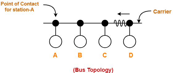
Consider the following scenario-


At the current instance,

  • If station A senses the carrier at its point of contact, then it will find the carrier free.
  • But the carrier is actually not free because station D is already transmitting its data.
  • If station A starts transmitting its data now, then it might lead to a collision with the data transmitted by station D.


Step-02: Detecting the Collision-


In CSMA / CD,

  • It is the responsibility of the transmitting station to detect the collision.
  • For detecting the collision, CSMA / CD implements the following condition.
  • This condition is followed by each station-


Transmission delay >= 2 x Propagation delay


Meaning-


According to this condition,

  • Each station must transmit the data packet of size whose transmission delay is at least twice its propagation delay.
  • If the size of data packet is smaller, then collision detection would not be possible.


Length Of Data Packet-


We know-

  • Transmission delay = Length of data packet (L) / Bandwidth (B)
  • Propagation delay = Distance between the two stations (D) / Propagation speed (V)


Substituting values in the above condition, we get-

 L / B >= 2 x D / V

Thus,


L >= 2 x B x D / V


Understanding the Condition To Detect Collision With Example


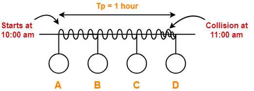
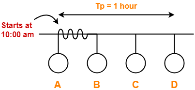
  • Consider at time 10:00 am, station A senses the carrier.
  • It finds the carrier free and starts transmitting its data packet to station D.
  • Let the propagation delay be 1 hour.

(We are considering station D for the worst case)


  • Let us consider the scenario at time 10:59:59:59 when the packet is about to reach the station D.
  • At this time, station D senses the carrier.
  • It finds the carrier free and starts transmitting its data packet.
  • Now, as soon as station D starts transmitting its data packet, a collision occurs with the data packet of station A at time 11:00 am.


  • After collision occurs, the collided signal starts travelling in the backward direction.
  • The collided signal takes 1 hour to reach the station A after the collision has occurred.
  • For station A to detect the collided signal, it must be still transmitting the data.
  • So, transmission delay of station A must be >= 1 hour + 1 hour >= 2 hours to detect the collision.
  • That is why, for detecting the collision, condition is Tt >= 2Tp.


Two cases are possible-


Case-01:


If no collided signal comes back during the transmission,

  • It indicates that no collision has occurred.
  • The data packet is transmitted successfully.


Case-02:


If the collided signal comes back during the transmission,

  • It indicates that the collision has occurred.
  • The data packet is not transmitted successfully.
  • Step-03 is followed.


Step-03: Releasing Jam Signal-


  • Jam signal is a 48 bit signal.
  • It is released by the transmitting stations as soon as they detect a collision.
  • It alerts the other stations not to transmit their data immediately after the collision.
  • Otherwise, there is a possibility of collision again with the same data packet.
  • Ethernet sends the jam signal at a frequency other than the frequency of data signals.
  • This ensures that jam signal does not collide with the data signals undergone collision.


Step-04: Waiting For Back Off Time-


  • After the collision, the transmitting station waits for some random amount of time called as back off time.
  • After back off time, it tries transmitting the data packet again.
  • If again the collision occurs, then station again waits for some random back off time and then tries again.
  • The station keeps trying until the back off time reaches its limit.
  • After the limit is reached, station aborts the transmission.
  • Back off time is calculated using Back Off Algorithm.


CSMA / CD Flowchart-


The following CSMA / CD flowchart represents the CSMA / CD procedure-


Efficiency-


Efficiency (η) = Useful Time / Total Time


Before a successful transmission,

  • There may occur many number of collisions.
  • 2 x Tp time is wasted during each collision.


Thus,

  • Useful time = Transmission delay of data packet = Tt
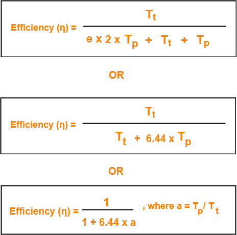
  • Useless time = Time wasted during collisions + Propagation delay of data packet = c x 2 x Tp + Tp
  • Here, c = Number of contention slots / collision slots.


Thus,


Here,

  • c is a variable.
  • This is because number of collisions that might occur before a successful transmission are variable.


Probabilistic Analysis shows-


Average number of collisions before a successful transmission = e


Substituting c = e in the above relation, we get-


Probabilistic Analysis-


Let us perform the probabilistic analysis to find the average number of collisions before a successful transmission.


Consider-

  • Number of stations connected to a CSMA / CD network = n
  • Probability of each station to transmit the data = p


Transmission will be successful only when-

  • One station transmits the data
  • Other (n-1) stations do not transmit the data.


Thus, Probability of successful transmission is given by-


Now, let us find the maximum value of Psuccessful transmission.

For maximum value, we put-


On solving,


At p = 1/n, we get the maximum value of Psuccessful transmission


Thus,

(Psuccessful transmission)max

= nC1 x 1/n x (1 – 1/n)n-1

= n x 1/n x (1 – 1/n)n-1

= (1 – 1/n)n-1


(Psuccessful transmission)max = (1 – 1/n)n-1


If there are sufficiently large number of stations i.e. n → ∞, then we have-


Number of times a station must try before successfully transmitting the data packet

= 1 / Pmax         (Using Poisson’s distribution)

= 1 / (1/e)

= e


From here, we conclude-

Average number of collisions that might occur before a successful transmission = e


Important Notes-


Note-01:


  • CSMA / CD is used in wired LANs.
  • CSMA / CD is standardized in IEEE 802.3


Note-02:


  • CSMA / CD only minimizes the recovery time.
  • It does not take any steps to prevent the collision until it has taken place.


Important Formulas-


  • Condition to detect collision: Transmission delay >= 2 x Propagation delay
  • Minimum length of data packets in CSMA / CD = 2 x Bandwidth x Distance / Speed
  • Efficiency of CSMA / CD = 1 / (1 + 6.44 x a) where a = Tp / Tt
  • Probability of successful transmission = nC1 x p x (1-p)n-1
  • Average number of collisions before a successful transmission = e


To gain better understanding about CSMA / CD,

Watch this Video Lecture


Next Article- Binary Exponential Back Off Algorithm


Get more notes and other study material of Computer Networks.

Watch video lectures by visiting our YouTube channel LearnVidFun.
Polling in Networking | Access Control Method

Access Control in Networking-


Before you go through this article, make sure that you have gone through the previous article on Access Control.


We have discussed-

  • Access Control is a mechanism that controls the access of stations to the transmission link.
  • Broadcast links require the access control mechanism.
  • There are various access control methods-


  1. Time Division Multiplexing
  2. Polling
  3. CSMA / CD
  4. Token Passing
  5. Aloha


In this article, we will discuss about polling.


Polling-


In this access control method,

  • A polling is conducted in which all the stations willing to send data participates.
  • The polling algorithm chooses one of the stations to send the data.
  • The chosen station sends the data to the destination.
  • After the chosen station has sent the data, the cycle repeats.


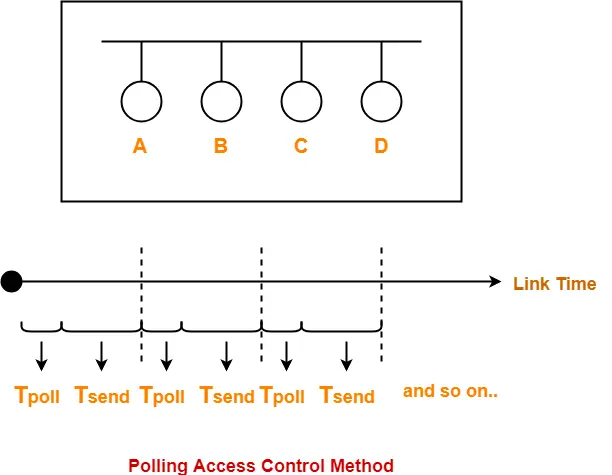
Example-


Here-

  • Tpoll = Time taken for polling
  • Tsend = Time taken for sending the data = Transmission delay + Propagation delay = Tt + Tp


Efficiency-


Efficiency (η) = Useful Time / Total Time


  • Useful time = Transmission delay of data packet = Tt
  • Useless time = Time wasted during polling + Propagation delay of data packet = Tpoll + Tp


Thus,


Advantages-


  • Unlike in Time Division Multiplexing, no slot is ever wasted.
  • It leads to maximum efficiency and bandwidth utilization.


Disadvantages-


  • Time is wasted during polling.
  • Link sharing is not fair since each station has the equal probability of winning in each round.
  • Few stations might starve for sending the data.


Important Formulas-


  • Efficiency (η) = Tt / (Tpoll + Tt + Tp)
  • Effective Bandwidth / Bandwidth Utilization / Throughput = Efficiency(η) x Bandwidth
  • Maximum Available Effective Bandwidth = Total number of stations x Bandwidth requirement of 1 station


To gain better understanding about Polling Access Control Method,

Watch this Video Lecture


Next Article- CSMA / CD | Access Control Method


Get more notes and other study material of Computer Networks.

Watch video lectures by visiting our YouTube channel LearnVidFun.
Time Division Multiplexing | Access Control

Access Control in Networking-


Before you go through this article, make sure that you have gone through the previous article on Access Control.


We have discussed-

  • Access Control is a mechanism that controls the access of stations to the transmission link.
  • Broadcast links require the access control mechanism.
  • There are various access control methods-


  1. Time Division Multiplexing
  2. Polling
  3. CSMA / CD
  4. Token Passing
  5. Aloha


In this article, we will discuss about Time Division Multiplexing (TDM).


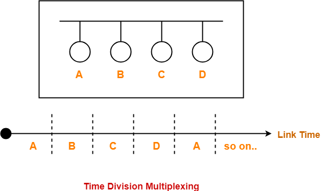
Time Division Multiplexing-


In Time Division Multiplexing (TDM),

  • Time of the link is divided into fixed size intervals called as time slots or time slices.
  • Time slots are allocated to the stations in Round Robin manner.
  • Each station transmit its data during the time slot allocated to it.
  • In case, station does not have any data to send, its time slot goes waste.


Example-


Size Of Time Slots-


The size of each time slot is kept such that each station gets sufficient time for the following tasks-

  • To put its data packet on to the transmission link
  • Last bit of the packet is able to get out of the transmission link


Thus,


Size of each time slot = Tt + Tp


where-

  • Tt = Transmission delay
  • Tp = Propagation delay


NOTE-


To keep the size of time slots constant,

  • We have assumed that all the stations want to send the packets of same size.
  • This keeps Tt constant for all the stations.
  • We have considered the worst case when both the stations are present at the two extreme ends.
  • This ensures Tp will be maximum and all the stations will get sufficient time to propagate their data.


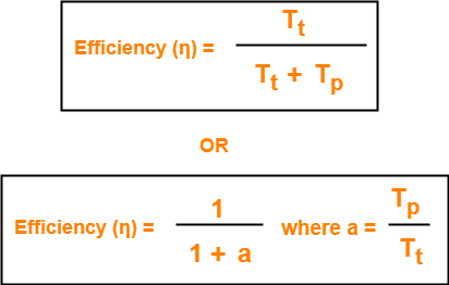
Efficiency-


Efficiency (η) = Useful Time / Total Time


  • Useful time = Transmission delay of data packet = Tt
  • Useless time = Propagation delay of data packet = Tp


Thus,


Important Formulas-


  • Size of each time slot in Time Division Multiplexing = Tt + Tp
  • Efficiency (η) = 1 / (1+a) where a = Tp / Tt
  • Effective Bandwidth / Bandwidth Utilization / Throughput = Efficiency(η) x Bandwidth
  • Maximum Available Effective Bandwidth = Total number of stations x Bandwidth requirement of 1 station


Disadvantage-


  • If any station does not have the data to send during its time slot, then its time slot goes waste.
  • This reduces the efficiency.
  • This time slot could have been allotted to some other station willing to send data.


PRACTICE PROBLEM BASED ON TIME DIVISION MULTIPLEXING (TDM)-


Problem-


If transmission delay and propagation delay of a packet in Time Division Multiplexing is 1 msec each at 4 Mbps bandwidth, then-

  1. Find the efficiency.
  2. Find the effective bandwidth.
  3. How many maximum stations can be connected to the network if each station requires 2 Kbps bandwidth?


Solution-


Given-

  • Transmission delay (Tt) = 1msec
  • Propagation delay (Tp) = 1msec
  • Bandwidth = 4 Mbps


Part-01:


For a TDM Network,


Efficiency (η) = 1 / 1+a where a = Tp / Tt


Calculating Value Of ‘a’-


a = Tp / Tt

a = 1 msec / 1 msec

a = 1


Calculating Efficiency-


Efficiency (η)

= 1 / (1+a)

= 1 / (1 + 1)

= 1 / 2

= 0.5

= 50%


Part-02:


We know-


Effective Bandwidth = Efficiency (η) x Bandwidth


Thus,

Effective Bandwidth

= 0.5 x 4 Mbps

= 2 Mbps


Part-03:


We know-


Maximum Effective Bandwidth

= Total number of stations x Bandwidth requirement of 1 station


Let the total number of stations that can be connected be N.

Then, we have-

2 Mbps = N x 2 Kbps

N = 1000

Thus, maximum 1000 stations can be connected.


To gain better understanding about Time Division Multiplexing (TDM),

Watch this Video Lecture


Next Article- Polling | Access Control Method


Get more notes and other study material of Computer Networks.

Watch video lectures by visiting our YouTube channel LearnVidFun.