Category: Computer Graphics

Bezier Curve in Computer Graphics | Examples

Bezier Curve-


Bezier Curve may be defined as-

  • Bezier Curve is parametric curve defined by a set of control points.
  • Two points are ends of the curve.
  • Other points determine the shape of the curve.


The concept of bezier curves was given by Pierre Bezier.


Bezier Curve Example-


The following curve is an example of a bezier curve-
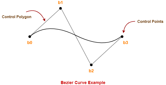


Here,

  • This bezier curve is defined by a set of control points b0, b1, b2 and b3.
  • Points b0 and b3 are ends of the curve.
  • Points b1 and b2 determine the shape of the curve.


Bezier Curve Properties-


Few important properties of a bezier curve are-


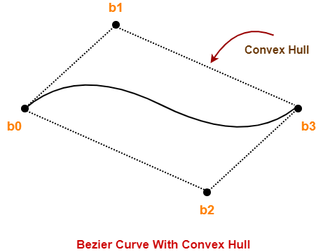
Property-01:


Bezier curve is always contained within a polygon called as convex hull of its control points.


Property-02:


  • Bezier curve generally follows the shape of its defining polygon.
  • The first and last points of the curve are coincident with the first and last points of the defining polygon.


Property-03:


The degree of the polynomial defining the curve segment is one less than the total number of control points.


Degree = Number of Control Points – 1


Property-04:


The order of the polynomial defining the curve segment is equal to the total number of control points.


Order = Number of Control Points


Property-05:


  • Bezier curve exhibits the variation diminishing property.
  • It means the curve do not oscillate about any straight line more often than the defining polygon.


Bezier Curve Equation-


A bezier curve is parametrically represented by-
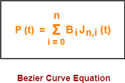


Here,

  • t is any parameter where 0 <= t <= 1
  • P(t) = Any point lying on the bezier curve
  • Bi = ith control point of the bezier curve
  • n = degree of the curve
  • Jn,i(t) = Blending function = C(n,i)ti(1-t)n-i where C(n,i) = n! / i!(n-i)!


Cubic Bezier Curve-


  • Cubic bezier curve is a bezier curve with degree 3.
  • The total number of control points in a cubic bezier curve is 4.


Example-


The following curve is an example of a cubic bezier curve-


Here,

  • This curve is defined by 4 control points b0, b1, b2 and b3.
  • The degree of this curve is 3.
  • So, it is a cubic bezier curve.


Cubic Bezier Curve Equation-


The parametric equation of a bezier curve is-


Substituting n = 3 for a cubic bezier curve, we get-


Expanding the above equation, we get-

P (t) = B0J3,0(t) + B1J3,1(t) + B2J3,2(t) + B3J3,3(t)     ………..(1)


Now,
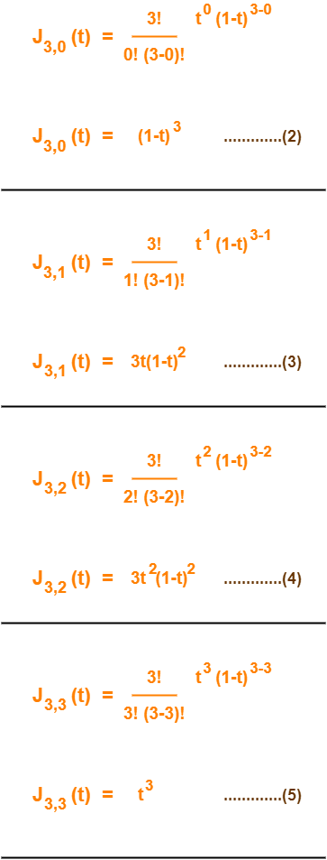


Using (2), (3), (4) and (5) in (1), we get-


P(t) = B0(1-t)3 + B13t(1-t)2 + B23t2(1-t) + B3t3


This is the required parametric equation for a cubic bezier curve.


Applications of Bezier Curves-


Bezier curves have their applications in the following fields-


1. Computer Graphics-


  • Bezier curves are widely used in computer graphics to model smooth curves.
  • The curve is completely contained in the convex hull of its control points.
  • So, the points can be graphically displayed & used to manipulate the curve intuitively.


2. Animation-


  • Bezier curves are used to outline movement in animation applications such as Adobe Flash and synfig.
  • Users outline the wanted path in bezier curves.
  • The application creates the needed frames for the object to move along the path.
  • For 3D animation, bezier curves are often used to define 3D paths as well as 2D curves.


3. Fonts-


  • True type fonts use composite bezier curves composed of quadratic bezier curves.
  • Modern imaging systems like postscript, asymptote etc use composite bezier curves composed of cubic bezier curves for drawing curved shapes.


PRACTICE PROBLEMS BASED ON BEZIER CURVE IN COMPUTER GRAPHICS-


Problem-01:


Given a bezier curve with 4 control points-

B0[1 0] , B1[3 3] , B2[6 3] , B3[8 1]

Determine any 5 points lying on the curve. Also, draw a rough sketch of the curve.


Solution-


We have-

  • The given curve is defined by 4 control points.
  • So, the given curve is a cubic bezier curve.


The parametric equation for a cubic bezier curve is-


P(t) = B0(1-t)3 + B13t(1-t)2 + B23t2(1-t) + B3t3


Substituting the control points B0, B1, B2 and B3, we get-

P(t) = [1 0](1-t)3 + [3 3]3t(1-t)2 + [6 3]3t2(1-t) + [8 1]t3      ……..(1)


Now,

To get 5 points lying on the curve, assume any 5 values of t lying in the range 0 <= t <= 1.

Let 5 values of t are 0, 0.2, 0.5, 0.7, 1


For t = 0:


Substituting t=0 in (1), we get-

P(0) = [1 0](1-0)3 + [3 3]3(0)(1-t)2 + [6 3]3(0)2(1-0) + [8 1](0)3

P(0) = [1 0] + 0 + 0 + 0

P(0) = [1 0]


For t = 0.2:


Substituting t=0.2 in (1), we get-

P(0.2) = [1 0](1-0.2)3 + [3 3]3(0.2)(1-0.2)2 + [6 3]3(0.2)2(1-0.2) + [8 1](0.2)3

P(0.2) = [1 0](0.8)3 + [3 3]3(0.2)(0.8)2 + [6 3]3(0.2)2(0.8) + [8 1](0.2)3

P(0.2) = [1 0] x 0.512 + [3 3] x 3 x 0.2 x 0.64 + [6 3] x 3 x 0.04 x 0.8 + [8 1] x 0.008

P(0.2) = [1 0] x 0.512 + [3 3] x 0.384 + [6 3] x 0.096 + [8 1] x 0.008

P(0.2) = [0.512 0] + [1.152 1.152] + [0.576 0.288] + [0.064 0.008]

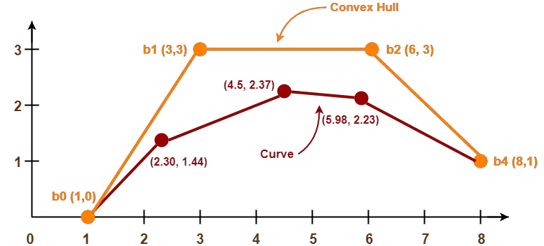
P(0.2) = [2.304 1.448]


For t = 0.5:


Substituting t=0.5 in (1), we get-

P(0.5) = [1 0](1-0.5)3 + [3 3]3(0.5)(1-0.5)2 + [6 3]3(0.5)2(1-0.5) + [8 1](0.5)3

P(0.5) = [1 0](0.5)3 + [3 3]3(0.5)(0.5)2 + [6 3]3(0.5)2(0.5) + [8 1](0.5)3

P(0.5) = [1 0] x 0.125 + [3 3] x 3 x 0.5 x 0.25 + [6 3] x 3 x 0.25 x 0.5 + [8 1] x 0.125

P(0.5) = [1 0] x 0.125 + [3 3] x 0.375 + [6 3] x 0.375 + [8 1] x 0.125

P(0.5) = [0.125 0] + [1.125 1.125] + [2.25 1.125] + [1 0.125]

P(0.5) = [4.5 2.375]


For t = 0.7:


Substituting t=0.7 in (1), we get-

P(t) = [1 0](1-t)3 + [3 3]3t(1-t)2 + [6 3]3t2(1-t) + [8 1]t3

P(0.7) = [1 0](1-0.7)3 + [3 3]3(0.7)(1-0.7)2 + [6 3]3(0.7)2(1-0.7) + [8 1](0.7)3

P(0.7) = [1 0](0.3)3 + [3 3]3(0.7)(0.3)2 + [6 3]3(0.7)2(0.3) + [8 1](0.7)3

P(0.7) = [1 0] x 0.027 + [3 3] x 3 x 0.7 x 0.09 + [6 3] x 3 x 0.49 x 0.3 + [8 1] x 0.343

P(0.7) = [1 0] x 0.027 + [3 3] x 0.189 + [6 3] x 0.441 + [8 1] x 0.343

P(0.7) = [0.027 0] + [0.567 0.567] + [2.646 1.323] + [2.744 0.343]

P(0.7) = [5.984 2.233]


For t = 1:


Substituting t=1 in (1), we get-

P(1) = [1 0](1-1)3 + [3 3]3(1)(1-1)2 + [6 3]3(1)2(1-1) + [8 1](1)3

P(1) = [1 0] x 0 + [3 3] x 3 x 1 x 0 + [6 3] x 3 x 1 x 0 + [8 1] x 1

P(1) = 0 + 0 + 0 + [8 1]

P(1) = [8 1]


Following is the required rough sketch of the curve-


To gain better understanding about Bezier Curves in Computer Graphics,

Watch this Video Lecture


Get more notes and other study material of Computer Graphics.

Watch video lectures by visiting our YouTube channel LearnVidFun.
3D Shearing in Computer Graphics | Definition | Examples

3D Transformations in Computer Graphics-


We have discussed-

  • Transformation is a process of modifying and re-positioning the existing graphics.
  • 3D Transformations take place in a three dimensional plane.


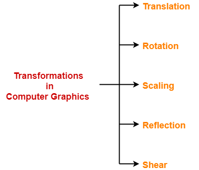
In computer graphics, various transformation techniques are-


  1. Translation
  2. Rotation
  3. Scaling
  4. Reflection
  5. Shear


In this article, we will discuss about 3D Shearing in Computer Graphics.


3D Shearing in Computer Graphics-


In Computer graphics,

3D Shearing is an ideal technique to change the shape of an existing object in a three dimensional plane.


In a three dimensional plane, the object size can be changed along X direction, Y direction as well as Z direction.

So, there are three versions of shearing-


  1. Shearing in X direction
  2. Shearing in Y direction
  3. Shearing in Z direction


Consider a point object O has to be sheared in a 3D plane.


Let-

  • Initial coordinates of the object O = (Xold, Yold, Zold)
  • Shearing parameter towards X direction = Shx
  • Shearing parameter towards Y direction = Shy
  • Shearing parameter towards Z direction = Shz
  • New coordinates of the object O after shearing = (Xnew, Ynew, Znew)


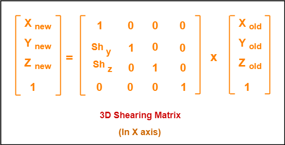
Shearing in X Axis-


Shearing in X axis is achieved by using the following shearing equations-

  • Xnew = Xold
  • Ynew = Yold + Shy x Xold
  • Znew = Zold + Shz x Xold


In Matrix form, the above shearing equations may be represented as-


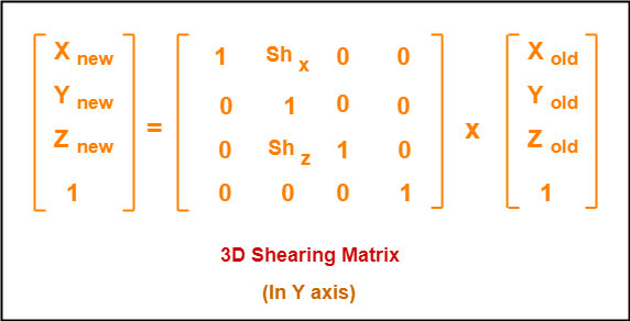
Shearing in Y Axis-


Shearing in Y axis is achieved by using the following shearing equations-

  • Xnew = Xold + Shx x Yold
  • Ynew = Yold
  • Znew = Zold + Shz x Yold


In Matrix form, the above shearing equations may be represented as-


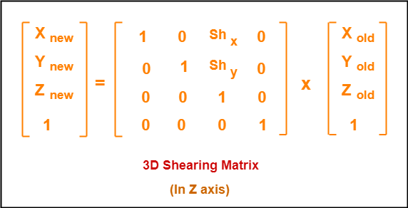
Shearing in Z Axis-


Shearing in Z axis is achieved by using the following shearing equations-

  • Xnew = Xold + Shx x Zold
  • Ynew = Yold + Shy x Zold
  • Znew = Zold


In Matrix form, the above shearing equations may be represented as-


PRACTICE PROBLEMS BASED ON 3D SHEARING IN COMPUTER GRAPHICS-


Problem-01:


Given a 3D triangle with points (0, 0, 0), (1, 1, 2) and (1, 1, 3). Apply shear parameter 2 on X axis, 2 on Y axis and 3 on Z axis and find out the new coordinates of the object.


Solution-


Given-

  • Old corner coordinates of the triangle = A (0, 0, 0), B(1, 1, 2), C(1, 1, 3)
  • Shearing parameter towards X direction (Shx) = 2
  • Shearing parameter towards Y direction (Shy) = 2
  • Shearing parameter towards Y direction (Shz) = 3


Shearing in X Axis-


For Coordinates A(0, 0, 0)


Let the new coordinates of corner A after shearing = (Xnew, Ynew, Znew).


Applying the shearing equations, we have-

  • Xnew = Xold = 0
  • Ynew = Yold + Shy x Xold = 0 + 2 x 0 = 0
  • Znew = Zold + Shz x Xold = 0 + 3 x 0 = 0


Thus, New coordinates of corner A after shearing = (0, 0, 0).


For Coordinates B(1, 1, 2)


Let the new coordinates of corner B after shearing = (Xnew, Ynew, Znew).


Applying the shearing equations, we have-

  • Xnew = Xold = 1
  • Ynew = Yold + Shy x Xold = 1 + 2 x 1 = 3
  • Znew = Zold + Shz x Xold = 2 + 3 x 1 = 5


Thus, New coordinates of corner B after shearing = (1, 3, 5).


For Coordinates C(1, 1, 3)


Let the new coordinates of corner C after shearing = (Xnew, Ynew, Znew).


Applying the shearing equations, we have-

  • Xnew = Xold = 1
  • Ynew = Yold + Shy x Xold = 1 + 2 x 1 = 3
  • Znew = Zold + Shz x Xold = 3 + 3 x 1 = 6


Thus, New coordinates of corner C after shearing = (1, 3, 6).

Thus, New coordinates of the triangle after shearing in X axis = A (0, 0, 0), B(1, 3, 5), C(1, 3, 6).


Shearing in Y Axis-


For Coordinates A(0, 0, 0)


Let the new coordinates of corner A after shearing = (Xnew, Ynew, Znew).


Applying the shearing equations, we have-

  • Xnew = Xold + Shx x Yold = 0 + 2 x 0 = 0
  • Ynew = Yold = 0
  • Znew = Zold + Shz x Yold = 0 + 3 x 0 = 0


Thus, New coordinates of corner A after shearing = (0, 0, 0).


For Coordinates B(1, 1, 2)


Let the new coordinates of corner B after shearing = (Xnew, Ynew, Znew).


Applying the shearing equations, we have-

  • Xnew = Xold + Shx x Yold = 1 + 2 x 1 = 3
  • Ynew = Yold = 1
  • Znew = Zold + Shz x Yold = 2 + 3 x 1 = 5


Thus, New coordinates of corner B after shearing = (3, 1, 5).


For Coordinates C(1, 1, 3)


Let the new coordinates of corner C after shearing = (Xnew, Ynew, Znew).


Applying the shearing equations, we have-

  • Xnew = Xold + Shx x Yold = 1 + 2 x 1 = 3
  • Ynew = Yold = 1
  • Znew = Zold + Shz x Yold = 3 + 3 x 1 = 6


Thus, New coordinates of corner C after shearing = (3, 1, 6).

Thus, New coordinates of the triangle after shearing in Y axis = A (0, 0, 0), B(3, 1, 5), C(3, 1, 6).


Shearing in Z Axis-


For Coordinates A(0, 0, 0)


Let the new coordinates of corner A after shearing = (Xnew, Ynew, Znew).


Applying the shearing equations, we have-

  • Xnew = Xold + Shx x Zold = 0 + 2 x 0 = 0
  • Ynew = Yold + Shy x Zold = 0 + 2 x 0 = 0
  • Znew = Zold = 0


Thus, New coordinates of corner A after shearing = (0, 0, 0).


For Coordinates B(1, 1, 2)


Let the new coordinates of corner B after shearing = (Xnew, Ynew, Znew).


Applying the shearing equations, we have-

  • Xnew = Xold + Shx x Zold = 1 + 2 x 2 = 5
  • Ynew = Yold + Shy x Zold = 1 + 2 x 2 = 5
  • Znew = Zold = 2


Thus, New coordinates of corner B after shearing = (5, 5, 2).


For Coordinates C(1, 1, 3)


Let the new coordinates of corner C after shearing = (Xnew, Ynew, Znew).


Applying the shearing equations, we have-

  • Xnew = Xold + Shx x Zold = 1 + 2 x 3 = 7
  • Ynew = Yold + Shy x Zold = 1 + 2 x 3 = 7
  • Znew = Zold = 3


Thus, New coordinates of corner C after shearing = (7, 7, 3).

Thus, New coordinates of the triangle after shearing in Z axis = A (0, 0, 0), B(5, 5, 2), C(7, 7, 3).


To gain better understanding about 3D Shearing in Computer Graphics,

Watch this Video Lecture


Next Article- Bezier Curves


Get more notes and other study material of Computer Graphics.

Watch video lectures by visiting our YouTube channel LearnVidFun.

3D Reflection in Computer Graphics | Definition | Examples

3D Transformations in Computer Graphics-


We have discussed-

  • Transformation is a process of modifying and re-positioning the existing graphics.
  • 3D Transformations take place in a three dimensional plane.


In computer graphics, various transformation techniques are-


  1. Translation
  2. Rotation
  3. Scaling
  4. Reflection
  5. Shear


In this article, we will discuss about 3D Reflection in Computer Graphics.


3D Reflection in Computer Graphics-


  • Reflection is a kind of rotation where the angle of rotation is 180 degree.
  • The reflected object is always formed on the other side of mirror.
  • The size of reflected object is same as the size of original object.


Consider a point object O has to be reflected in a 3D plane.


Let-

  • Initial coordinates of the object O = (Xold, Yold, Zold)
  • New coordinates of the reflected object O after reflection = (Xnew, Ynew,Znew)


In 3 dimensions, there are 3 possible types of reflection-


  • Reflection relative to XY plane
  • Reflection relative to YZ plane
  • Reflection relative to XZ plane


Reflection Relative to XY Plane:


This reflection is achieved by using the following reflection equations-

  • Xnew = Xold
  • Ynew = Yold
  • Znew = -Zold


In Matrix form, the above reflection equations may be represented as-


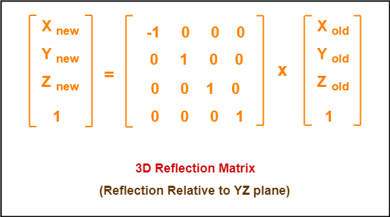
Reflection Relative to YZ Plane:


This reflection is achieved by using the following reflection equations-

  • Xnew = -Xold
  • Ynew = Yold
  • Znew = Zold


In Matrix form, the above reflection equations may be represented as-


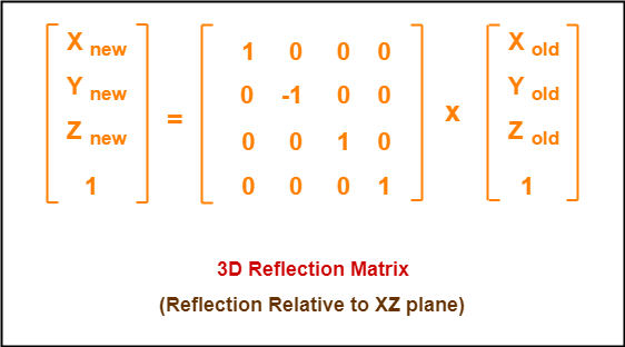
Reflection Relative to XZ Plane:


This reflection is achieved by using the following reflection equations-

  • Xnew = Xold
  • Ynew = -Yold
  • Znew = Zold


In Matrix form, the above reflection equations may be represented as-


PRACTICE PROBLEMS BASED ON 3D REFLECTION IN COMPUTER GRAPHICS-


Problem-01:


Given a 3D triangle with coordinate points A(3, 4, 1), B(6, 4, 2), C(5, 6, 3). Apply the reflection on the XY plane and find out the new coordinates of the object.


Solution-


Given-

  • Old corner coordinates of the triangle = A (3, 4, 1), B(6, 4, 2), C(5, 6, 3)
  • Reflection has to be taken on the XY plane


For Coordinates A(3, 4, 1)


Let the new coordinates of corner A after reflection = (Xnew, Ynew, Znew).


Applying the reflection equations, we have-

  • Xnew = Xold = 3
  • Ynew = Yold = 4
  • Znew = -Zold = -1


Thus, New coordinates of corner A after reflection = (3, 4, -1).


For Coordinates B(6, 4, 2)


Let the new coordinates of corner B after reflection = (Xnew, Ynew, Znew).


Applying the reflection equations, we have-

  • Xnew = Xold = 6
  • Ynew = Yold = 4
  • Znew = -Zold = -2


Thus, New coordinates of corner B after reflection = (6, 4, -2).


For Coordinates C(5, 6, 3)


Let the new coordinates of corner C after reflection = (Xnew, Ynew, Znew).


Applying the reflection equations, we have-

  • Xnew = Xold = 5
  • Ynew = Yold = 6
  • Znew = -Zold = -3


Thus, New coordinates of corner C after reflection = (5, 6, -3).

Thus, New coordinates of the triangle after reflection = A (3, 4, -1), B(6, 4, -2), C(5, 6, -3).


Problem-02:


Given a 3D triangle with coordinate points A(3, 4, 1), B(6, 4, 2), C(5, 6, 3). Apply the reflection on the XZ plane and find out the new coordinates of the object.


Solution-


Given-

  • Old corner coordinates of the triangle = A (3, 4, 1), B(6, 4, 2), C(5, 6, 3)
  • Reflection has to be taken on the XZ plane


For Coordinates A(3, 4, 1)


Let the new coordinates of corner A after reflection = (Xnew, Ynew, Znew).


Applying the reflection equations, we have-

  • Xnew = Xold = 3
  • Ynew = -Yold = -4
  • Znew = Zold = 1


Thus, New coordinates of corner A after reflection = (3, -4, 1).


For Coordinates B(6, 4, 2)


Let the new coordinates of corner B after reflection = (Xnew, Ynew, Znew).


Applying the reflection equations, we have-

  • Xnew = Xold = 6
  • Ynew = -Yold = -4
  • Znew = Zold = 2


Thus, New coordinates of corner B after reflection = (6, -4, 2).


For Coordinates C(5, 6, 3)


Let the new coordinates of corner C after reflection = (Xnew, Ynew, Znew).


Applying the reflection equations, we have-

  • Xnew = Xold = 5
  • Ynew = -Yold = -6
  • Znew = Zold = 3


Thus, New coordinates of corner C after reflection = (5, -6, 3).

Thus, New coordinates of the triangle after reflection = A (3, -4, 1), B(6, -4, 2), C(5, -6, 3).


To gain better understanding about 3D Reflection in Computer Graphics,

Watch this Video Lecture


Next Article- 3D Shearing in Computer Graphics


Get more notes and other study material of Computer Graphics.

Watch video lectures by visiting our YouTube channel LearnVidFun.
3D Scaling in Computer Graphics | Definition | Examples

3D Transformations in Computer Graphics-


We have discussed-

  • Transformation is a process of modifying and re-positioning the existing graphics.
  • 3D Transformations take place in a three dimensional plane.


In computer graphics, various transformation techniques are-


  1. Translation
  2. Rotation
  3. Scaling
  4. Reflection
  5. Shear


In this article, we will discuss about 3D Scaling in Computer Graphics.


3D Scaling in Computer Graphics-


In computer graphics, scaling is a process of modifying or altering the size of objects.


  • Scaling may be used to increase or reduce the size of object.
  • Scaling subjects the coordinate points of the original object to change.
  • Scaling factor determines whether the object size is to be increased or reduced.
  • If scaling factor > 1, then the object size is increased.
  • If scaling factor < 1, then the object size is reduced.


Consider a point object O has to be scaled in a 3D plane.


Let-

  • Initial coordinates of the object O = (Xold, Yold,Zold)
  • Scaling factor for X-axis = Sx
  • Scaling factor for Y-axis = Sy
  • Scaling factor for Z-axis = Sz
  • New coordinates of the object O after scaling = (Xnew, Ynew, Znew)


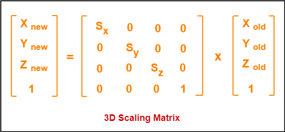
This scaling is achieved by using the following scaling equations-

  • Xnew = Xold x Sx
  • Ynew = Yold x Sy
  • Znew = Zold x Sz


In Matrix form, the above scaling equations may be represented as-


PRACTICE PROBLEMS BASED ON 3D SCALING IN COMPUTER GRAPHICS-


Problem-01:


Given a 3D object with coordinate points A(0, 3, 3), B(3, 3, 6), C(3, 0, 1), D(0, 0, 0). Apply the scaling parameter 2 towards X axis, 3 towards Y axis and 3 towards Z axis and obtain the new coordinates of the object.


Solution-


Given-

  • Old coordinates of the object  = A (0, 3, 3), B(3, 3, 6), C(3, 0, 1), D(0, 0, 0)
  • Scaling factor along X axis = 2
  • Scaling factor along Y axis = 3
  • Scaling factor along Z axis = 3


For Coordinates A(0, 3, 3)


Let the new coordinates of A after scaling = (Xnew, Ynew, Znew).


Applying the scaling equations, we have-

  • Xnew = Xold x Sx = 0  x 2 = 0
  • Ynew = Yold x Sy = 3 x 3 = 9
  • Znew = Zold x Sz = 3 x 3 = 9


Thus, New coordinates of corner A after scaling = (0, 9, 9).


For Coordinates B(3, 3, 6)


Let the new coordinates of B after scaling = (Xnew, Ynew, Znew).


Applying the scaling equations, we have-

  • Xnew = Xold x Sx = 3  x 2 = 6
  • Ynew = Yold x Sy = 3 x 3 = 9
  • Znew = Zold x Sz = 6 x 3 = 18


Thus, New coordinates of corner B after scaling = (6, 9, 18).


For Coordinates C(3, 0, 1)


Let the new coordinates of C after scaling = (Xnew, Ynew, Znew).


Applying the scaling equations, we have-

  • Xnew = Xold x Sx = 3  x 2 = 6
  • Ynew = Yold x Sy = 0 x 3 = 0
  • Znew = Zold x Sz = 1 x 3 = 3


Thus, New coordinates of corner C after scaling = (6, 0, 3).


For Coordinates D(0, 0, 0)


Let the new coordinates of D after scaling = (Xnew, Ynew, Znew).


Applying the scaling equations, we have-

  • Xnew = Xold x Sx = 0  x 2 = 0
  • Ynew = Yold x Sy = 0 x 3 = 0
  • Znew = Zold x Sz = 0 x 3 = 0


Thus, New coordinates of corner D after scaling = (0, 0, 0).


To gain better understanding about 3D Scaling in Computer Graphics,

Watch this Video Lecture


Next Article- 3D Reflection in Computer Graphics


Get more notes and other study material of Computer Graphics.

Watch video lectures by visiting our YouTube channel LearnVidFun.
3D Rotation in Computer Graphics | Definition | Examples

3D Transformations in Computer Graphics-


We have discussed-

  • Transformation is a process of modifying and re-positioning the existing graphics.
  • 3D Transformations take place in a three dimensional plane.


In computer graphics, various transformation techniques are-


  1. Translation
  2. Rotation
  3. Scaling
  4. Reflection
  5. Shear


In this article, we will discuss about 3D Rotation in Computer Graphics.


3D Rotation in Computer Graphics-


In Computer graphics,

3D Rotation is a process of rotating an object with respect to an angle in a three dimensional plane.


Consider a point object O has to be rotated from one angle to another in a 3D plane.


Let-

  • Initial coordinates of the object O = (Xold, Yold, Zold)
  • Initial angle of the object O with respect to origin = Φ
  • Rotation angle = θ
  • New coordinates of the object O after rotation = (Xnew, Ynew, Znew)


In 3 dimensions, there are 3 possible types of rotation-

  • X-axis Rotation
  • Y-axis Rotation
  • Z-axis Rotation


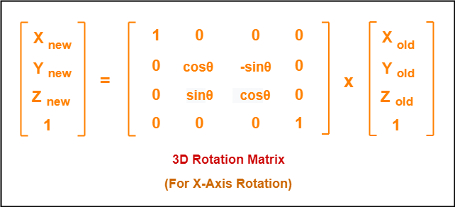
For X-Axis Rotation-


This rotation is achieved by using the following rotation equations-

  • Xnew = Xold
  • Ynew = Yold x cosθ – Zold x sinθ
  • Znew = Yold x sinθ + Zold x cosθ


In Matrix form, the above rotation equations may be represented as-


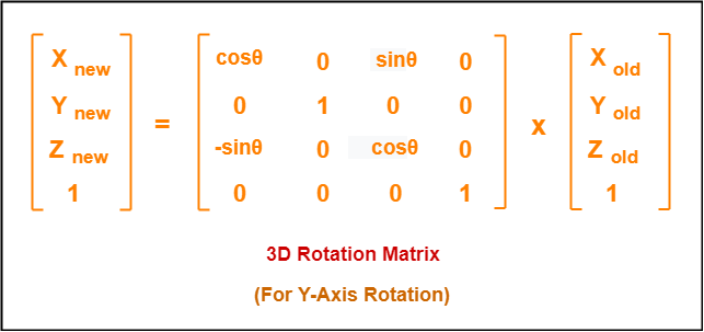
For Y-Axis Rotation-


This rotation is achieved by using the following rotation equations-

  • Xnew = Zold x sinθ + Xold x cosθ
  • Ynew = Yold
  • Znew = Yold x cosθ – Xold x sinθ


In Matrix form, the above rotation equations may be represented as-


For Z-Axis Rotation-


This rotation is achieved by using the following rotation equations-

  • Xnew = Xold x cosθ – Yold x sinθ
  • Ynew = Xold x sinθ + Yold x cosθ
  • Znew = Zold


In Matrix form, the above rotation equations may be represented as-


PRACTICE PROBLEMS BASED ON 3D ROTATION IN COMPUTER GRAPHICS-


Problem-01:


Given a homogeneous point (1, 2, 3). Apply rotation 90 degree towards X, Y and Z axis and find out the new coordinate points.


Solution-


Given-

  • Old coordinates = (Xold, Yold, Zold) = (1, 2, 3)
  • Rotation angle = θ = 90º


For X-Axis Rotation-


Let the new coordinates after rotation = (Xnew, Ynew, Znew).


Applying the rotation equations, we have-

  • Xnew = Xold = 1
  • Ynew = Yold x cosθ – Zold x sinθ = 2 x cos90° – 3 x sin90° = 2 x 0 – 3 x 1 = -3
  • Znew = Yold x sinθ + Zold x cosθ = 2 x sin90° + 3 x cos90° = 2 x 1 + 3 x 0 = 2


Thus, New coordinates after rotation = (1, -3, 2).


For Y-Axis Rotation-


Let the new coordinates after rotation = (Xnew, Ynew, Znew).


Applying the rotation equations, we have-

  • Xnew = Zold x sinθ + Xold x cosθ = 3 x sin90° + 1 x cos90° = 3 x 1 + 1 x 0 = 3
  • Ynew = Yold = 2
  • Znew = Yold x cosθ – Xold x sinθ = 2 x cos90° – 1 x sin90° = 2 x 0 – 1 x 1 = -1


Thus, New coordinates after rotation = (3, 2, -1).


For Z-Axis Rotation-


Let the new coordinates after rotation = (Xnew, Ynew, Znew).


Applying the rotation equations, we have-

  • Xnew = Xold x cosθ – Yold x sinθ = 1 x cos90° – 2 x sin90° = 1 x 0 – 2 x 1 = -2
  • Ynew = Xold x sinθ + Yold x cosθ = 1 x sin90° + 2 x cos90° = 1 x 1 + 2 x 0 = 1
  • Znew = Zold = 3


Thus, New coordinates after rotation = (-2, 1, 3).


To gain better understanding about 3D Rotation in Computer Graphics,

Watch this Video Lecture


Next Article- 3D Scaling in Computer Graphics


Get more notes and other study material of Computer Graphics.

Watch video lectures by visiting our YouTube channel LearnVidFun.